Sign In
Upload
Download
Table of Contents
Contents
Add to my manuals
Delete from my manuals
Share
URL of this page:
HTML Link:
Bookmark this page
Add
Manual will be automatically added to "My Manuals"
Print this page
×
Bookmark added
×
Added to my manuals
Manuals
Brands
ASRock Industrial Manuals
Computer Hardware
NUC BOX-1260P
User manual
ASRock Industrial NUC BOX-1260P User Manual
Hide thumbs
1
2
3
Table Of Contents
4
5
6
7
8
9
10
11
12
13
14
15
16
17
18
19
20
21
22
23
24
25
26
27
28
29
30
31
32
33
34
35
36
37
38
39
40
41
42
43
44
45
46
47
48
page
of
48
Go
/
48
Contents
Table of Contents
Bookmarks
Table of Contents
Table of Contents
Chapter 1 Introduction
Package Contents
Product Specifications
Block Diagram
Chapter 2 Product Overview
Front View
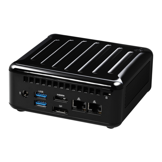
Rear View
Inside View
Chapter 3 Hardware Installation
How to Remove the Bottom Case
How to Install the Wifi Module
How to Remove the M.2 SSD (Type 2280) and the Bracket
How to Install the M.2 SSD (Type 2260)
How to Install the 2.5-Inch Hard Drive
How to Install the Memory Modules (DDR4)
Chapter 4 Motherboard
Motherboard Layout
Motherboard Specifications
Onboard Headers and Connectors
Expansion Slots (M.2 Slots)
Chapter 5 UEFI Setup Utility
Introduction
Main Screen
Advanced Screen
Hardware Health Event Monitoring Screen
Security Screen
Boot Screen
Exit Screen
Chapter 6 Software Support
Install Operating System
Advertisement
Quick Links
Download this manual
NUC BOX-1260P
NUC BOX-1240P
NUC BOX-1220P
User Manual
Version 1.0
Published May 2022
Table of
Contents
Previous
Page
Next
Page
1
2
3
4
5
Advertisement
Table of Contents
Need help?
Do you have a question about the NUC BOX-1260P and is the answer not in the manual?
Ask a question
Questions and answers
Related Manuals for ASRock Industrial NUC BOX-1260P
Computer Hardware ASRock Industrial NUC BOX-J6412 User Manual
(46 pages)
Computer Hardware ASRock Industrial NUC BOX-1240P User Manual
(48 pages)
Computer Hardware ASRock Industrial NUC BOX-N97 Quick Start Manual
(2 pages)
Computer Hardware ASRock Industrial NUC-1360P/D4 User Manual
(42 pages)
Computer Hardware ASRock Industrial NUC-1335UE/D4 User Manual
(42 pages)
Computer Hardware ASRock Industrial 4X4 BOX-7840U User Manual
(48 pages)
Computer Hardware ASRock Industrial IMB-1239-WV Quick Start Manual
(2 pages)
Computer Hardware ASRock Industrial IMB-1240-WV Settings Manual
(2 pages)
Computer Hardware ASRock Industrial IMB-1714 User Manual
(63 pages)
Computer Hardware ASRock Industrial IMB-1241 Settings Manual
(2 pages)
Computer Hardware ASRock Industrial SBC-250J Settings Manual
(2 pages)
Computer Hardware ASRock Industrial SBC-260 User Manual
(50 pages)
Computer Hardware ASRock Industrial iBOX 250 Series User Manual
(60 pages)
Computer Hardware ASRock Industrial IMB-1314 Manual
(2 pages)
Computer Hardware ASRock Industrial NUC-N97 User Manual
(42 pages)
Computer Hardware ASRock Industrial IMB-1003J Settings Manual
(2 pages)
This manual is also suitable for:
Nuc box-1240p
Nuc box-1220p
Table of Contents
Print
Rename the bookmark
Delete bookmark?
Delete from my manuals?
Login
Sign In
OR
Sign in with Facebook
Sign in with Google
Upload manual
Upload from disk
Upload from URL


Need help?
Do you have a question about the NUC BOX-1260P and is the answer not in the manual?
Questions and answers