
Subscribe to Our Youtube Channel
Related Manuals for ASRock Industrial NUC-1360P/D4


Summary of Contents for ASRock Industrial NUC-1360P/D4
- Page 1 NUC-1360P/D4 NUC-1340P/D4 NUC-1365UE/D4 NUC-1345UE/D4 NUC-1315UE/D4 NUC-1315U/D4 User Manual Version 1.1 Updated March 22, 2023 Copyright©2023 ASRockInd INC. All rights reserved.
- Page 2 Version 1.0 Published December 30, 2022 Copyright©2023 ASRockInd INC. All rights reserved. Copyright Notice: No part of this documentation may be reproduced, transcribed, transmitted, or translated in any language, in any form or by any means, except duplication of documentation by the purchaser for backup purpose, without written consent of ASRockInd Inc.
- Page 3 The terms HDMI® and HDMI High-Definition Multimedia Interface, and the HDMI logo are trademarks or registered trademarks of HDMI Licensing LLC in the United States and other countries. CAUTION: RISK OF EXPLOSION IF BATTERY IS REPLACED BY AN INCORRECT TYPE. DISPOSE OF USED BATTERIES ACCORDING TO THE INSTRUCTIONS.
-
Page 4: Table Of Contents
Contents Chapter 1 Introduction Package Contents Specifications Motherboard Layout I/O Panel Block Diagram Chapter 2 Installation Screw Holes Pre-installation Precautions Installation of Memory Modules Expansion Slots Onboard Headers and Connectors Installation of ROM Socket Chapter 3 UEFI SETUP UTILITY Introduction 3.1.1 Entering BIOS Setup 3.1.2... -
Page 6: Chapter 1 Introduction
NUC 1300/D4 Series Chapter 1 Introduction Thank you for purchasing ASRockInd NUC-1360P/D4 / NUC-1340P/D4 / NUC- 1365UE/D4 / NUC-1345UE/D4 / NUC-1315UE/D4 / NUC-1315U/D4 motherboard, a reliable motherboard produced under ASRockInd’s consistently stringent quality control. It delivers excellent performance with robust design conforming to ASRock- Ind’s commitment to quality and endurance. -
Page 7: Specifications
1.2 Specifications Form NUC (4.09-in x 4.02-in x 1.5-in, 10.4 cm x 10.2 cm x 3.8 Dimensions Factor Intel® 13th Gen (Raptor Lake-P) Core™ Processors NUC-1360P/D4 (i7-1360P, 4P+8E) NUC-1340P/D4 (i5-1340P, 4P+8E) NUC-1365UE/D4 (i7-1365UE, 2P+8E) Processor NUC-1345UE/D4 (i5-1345UE, 2P+8E) System NUC-1315UE/D4 (i3-1315UE, 2P+4E) - Page 8 NUC 1300/D4 Series 2 x USB 3.2 Gen2 (Type A) 1 x USB4/Thunderbolt™ 4 (Type-C, supports DP1.4a display output) Front I/O 1 x USB 3.2 Gen2 (Type-C, supports DP1.4a display output) Audio 1 (headphone & microphone jack) 2 x USB 2.0 (1 x 2.00 pitch header) Internal 1 x COM(RS-232/RS-422/RS-485) Connector...
-
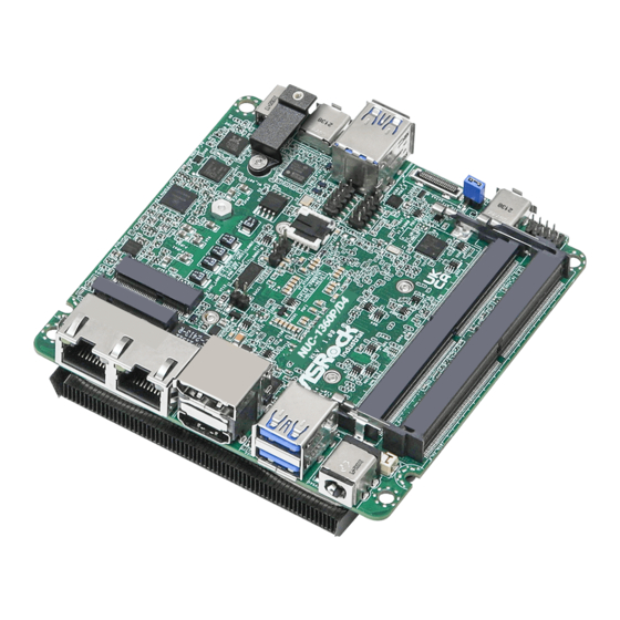
Page 9: Motherboard Layout
1.3 Motherboard Layout AUDIO1 TC_T0 (Type C): BIOS USB4 / Thunderbolt 4 USB3_3_4 (USB3.2 Gen2): Bottom: USB3_3 USB2_7_8 Top: USB3_4 HDMI_DP_1: COM1 Bottom: HDMI Top: DP SATA3_0 USB3_1_2 Industrial (USB3.2 Gen2): Bottom: USB3_1 Top: USB3_2 TC_UD1 (Type C): USB3/DP DDR4_B1 (Support DDR4 Only) DC_JACK1 DDR4_A1 (Support DDR4 Only) 1 : M.2 Key-M Socket (M2_M1) -
Page 10: I/O Panel
NUC 1300/D4 Series 1.4 I/O Panel Front I/O : Rear I/O : USB3/DP Type-C Port (TC_UD1) RJ-45 LAN Port (LAN2)* USB 3.2 Gen2 Ports (USB3_3_4) HDMI Port (HDMI1) ™ DisplayPort (DP1) USB4/Thunderbolt 4 Type-C Port (TC_T0) USB 3.2 Gen2 Ports (USB3_1_2) Audio Jack (AUDIO1) 10 DC-in Jack (DC_IN1) RJ-45 LAN Port (LAN1)*... -
Page 11: Block Diagram
1.5 Block Diagram DDR4 3200MHZ TCP0+USB2#5 Type C SO-DIMM INTEL Connector DDR4 3200MHZ TCP1+USB2#6 SO-DIMM Type C Connector SATA(#0) SATA Port TMDS TCP2 HDMI HDMI Connector RETIMER PCIe x1(#6) CNVi M.2 Key E USB2.0(P10) TCP3 AUX/DDC DP++ SWITCH Connector CPU PCIe x4 Port A(3:0) M.2 Key M 2xUSB3.2 Gen2(#1, #2) 2x USB3.2 Gen2... -
Page 12: Chapter 2 Installation
NUC 1300/D4 Series Chapter 2 Installation NUC (4.09-in x 4.02-in x 1.5-in, 10.4 cm x 10.2 cm x 3.8 cm) This is a form factor motherboard. Before you install the motherboard, study the configuration of your chassis to ensure that the motherboard fits into it. Make sure to unplug the power cord before installing or removing the motherboard. -
Page 13: Installation Of Memory Modules
2.3 Installation of Memory Modules NUC-1360P/D4 / NUC-1340P/D4 / NUC-1365UE/D4 / NUC-1345UE/D4 / NUC- 1315UE/D4 / NUC-1315U/D4 provides two 260-pin DDR4 (Double Data Rate 4) slots, and supports Dual Channel Memory Technology. Step 1. Align a SO-DIMM on the slot such that the notch on the SO-DIMM matches the break on the slot. -
Page 14: Expansion Slots
NUC 1300/D4 Series 2.4 Expansion Slots There are 2 M.2 sockets on this motherboard. M.2 for SSD: 1 x M.2 (KEY M, 2242/2260/2280) with PCIe Gen4 x 4 for SSD. * M.2 Key M 2280 (Supported by bracket) M.2 for Wi-Fi: 1 x M.2 (Key E, 2230) with PCIe x1, USB 2.0 and CNVi for Wireless. M.2 Key-M M.2 Key-E Socket (M2_M1) -
Page 15: Onboard Headers And Connectors
2.5 Onboard Headers and Connectors Onboard headers and connectors are NOT jumpers. Do NOT place jumper caps over these headers and connectors. Placing jumper caps over the headers and connectors will cause per- manent damage to the motherboard! USB 2.0 Connector (9-pin USB2_7_8) (see p. - Page 16 NUC 1300/D4 Series SATA3 Port (SATA3_0) (see p. 4, No. 5) The Serial ATA3 (SATA3) connector supports SATA data cables for internal storage devices. The current SATA3 interface allows up to 6.0 Gb/s data transfer rate. JP1 Header 1-2: SIO AT Mode (Default Open: SIO ATX Mode) (8-pin JP1) 4-6: Clear CMOS...
- Page 17 Back Side : Power Button (PWR_BTN1) Fan Connector +12V (FAN1) FAN_SPEED FAN_SPEED_CONTROL Battery Connector BAT1 BAT1 (BAT1) ESPI Header (ESPI1) ESPI_CLK ESPI_CS# ESPI_RESET# SMB_CLK_MAIN SMB_DATA_MAIN ESPI_IO0 ESPI_IO1 ESPI_IO2 ESPI_IO3 +3VSB GPIO_TEST# ESPI_ALERT#...
-
Page 18: Installation Of Rom Socket
2.6 Installation of ROM Socket * Do not apply force to the actuator cover after IC inserted. * Do not apply force to actuator cover when it is opening over 120 degrees, Otherwise, the actuator cover may be broken. * The yellow dot (Pin1) on the ROM must be installed at pin1 position of the socket. -
Page 19: Chapter 3 Uefi Setup Utility
Chapter 3 UEFI SETUP UTILITY 3.1 Introduction ASRock Industrial UEFI (Unified Extensible Firmware Interface) is a BIOS utility which offers tweak-friendly options in an advanced viewing interface. The UEFI system works with a USB mouse and offers users a faster, sleeker experience. -
Page 20: Uefi Menu Bar
NUC 1300/D4 Series 3.1.2 UEFI Menu Bar The top of the screen has a menu bar with the following selections: Main For setting system time/date information For advanced system configurations Advanced H/W Monitor Displays current hardware status Security For security settings Boot For configuring boot settings and boot priority Exit... -
Page 21: Navigation Keys
3.1.3 Navigation Keys Use < > key or < > key to choose among the selections on the menu bar, and use < > key or < > key to move the cursor up or down to select items, then press <Enter>... -
Page 22: Main Screen (Advanced Mode)
NUC 1300/D4 Series 3.2 Main Screen (Advanced Mode) When you enter the UEFI SETUP UTILITY, the Main screen will appear and display the system overview. Because the UEFI software is constantly being updated, the following UEFI setup screens and descriptions are for reference purpose only, and they may not exactly match what you see on your screen. -
Page 23: Advanced Screen
3.3 Advanced Screen In this section, you may set the configurations for the following items: CPU Configuration, Chipset Configuration, Super IO Configuration, AMT Configura- tion, ACPI Configuration, USB Configuration and Trusted Computing. Setting wrong values in this section may cause the system to malfunction. Instant Flash Instant Flash is a UEFI flash utility embedded in Flash ROM. -
Page 24: Cpu Configuration
NUC 1300/D4 Series 3.3.1 CPU Configuration Intel Hyper Threading Technology Intel Hyper Threading Technology allows multiple threads to run on each core, so that the overall performance on threaded software is improved. Configuration options: [Enabled] [Disabled] Active Processor P-Cores This allows you to select the number of cores to enable in each processor package. Active Processor E-Cores This allows you to select the number of E-Cores to enable in each processor package. - Page 25 Enhanced Halt State (C1E) The option allows you to enable Enhanced Halt State (C1E) for lower power consumption. Configuration options: [Enabled] [Disabled] Package C State Support The option allows you to enable CPU, PCIe, Memory, Graphics C State Support for power saving.
- Page 26 NUC 1300/D4 Series Intel Turbo Boost Technology Intel Turbo Boost Technology enables the processor to run above its base operating frequency when the operating system requests the highest performance state. The default value is [Enabled]. Configuration options: [Enabled] [Disabled] CPU Thermal Throttling CPU Thermal Throttling allows you to enable CPU internal thermal control mecha- nisms to keep the CPU from overheating.
-
Page 27: Chipset Configuration
3.3.2 Chipset Configuration VT-d Intel® Virtualization Technology for Directed I/O helps your virtual machine monitor better utilize hardware by improving application compatibility and reliability, and providing additional levels of manageability, security, isolation, and I/O performance. Configuration options: [Enabled] [Disabled] Re-Size BAR Support If system has Resizable BAR capable PCIe Devices, this option enables or disables Resizable BAR Support. - Page 28 NUC 1300/D4 Series In-Band ECC Support This allows you to enable or disable In-Band ECC. Configuration options: [Enabled] [Disabled] Render Standby Power down the render unit when the GPU is idle for lower power consumption. Configuration options: [Enabled] [Disabled] Onboard LAN1 This allows you to enable or disable the Onboard LAN1 feature.
-
Page 29: Storage Configuration
3.3.3 Storage Configuration SATA Controller(s) The option allows you to enable or disable the SATA controllers. Configuration options: [Enabled] [Disabled] SATA Mode Selection AHCI supports new features that improve performance. Configuration option: [AHCI] AHCI (Advanced Host Controller Interface) supports NCQ and other new features that will improve SATA disk performance. - Page 30 NUC 1300/D4 Series SATA Aggressive Link Power Management SATA Aggressive Link Power Management allows SATA devices to enter a low power state during periods of inactivity to save power. It is supported only by AHCI mode. Configuration options: [Enabled] [Disabled] Hard Disk S.M.A.R.T.
-
Page 31: Super Io Configuration
3.3.4 Super IO Configuration COM1 Configuration Use this to set parameters of COM1. Type Select Use this to select COM1 port type: [RS232], [RS422] or [RS485]. WDT Timeout Reset Use this to set the Watch Dog Timer. Configuration options: [Enabled] [Disabled]... -
Page 32: Amt Configuration
NUC 1300/D4 Series 3.3.5 AMT Configuration USB Provisioning of AMT Use this to enable or disable AMT USB Provisioning. The default is [Disabled]. MAC Pass Through The option enables or disables MAC Pass Through function. Dynamic Lan Switch This allows switching AMT support from Integrated LAN to Discrete LAN. Activate Remote Assistance Process Trigger CIRA boot. - Page 33 One Click Recovery(OCR) Configuration Configuration setting for One Click Recovery. This allows access for AMT to boot a recovery OS application Remote Platform Erase Configuration Remote Platform Erase configuration menu. MEBx This Formset contains forms for configuring MEBx.
-
Page 34: Acpi Configuration
NUC 1300/D4 Series 3.3.6 ACPI Configuration Suspend to RAM Suspend to RAM allows you to select [Disabled] for ACPI suspend type S1. It is recommended to select [Auto] for ACPI S3 power saving. Configuration options: [Auto] [Disabled] Onboard LAN Power On Use this item to enable or disable onboard LAN to turn on the system from the power-soft-off mode. -
Page 35: Usb Configuration
3.3.7 USB Configuration USB Power Control Use this option to control USB power. Configuration options: [Always Enabled] [Default Setting]... -
Page 36: Trusted Computing
NUC 1300/D4 Series 3.3.8 Trusted Computing NOTE: Options vary depending on the version of your connected TPM module. Security Device Support Security Device Support allows you to enable or disable BIOS support for security device. O.S. will not show Security Device. TCG EFI protocol and INT1A interface will not be available. - Page 37 Platform Hierarchy This item allows you to enable or disable Platform Hierarchy. Configuration options: [Enabled] [Disabled] Storage Hierarchy This item allows you to enable or disable Storage Hierarchy. Configuration options: [Enabled] [Disabled] Endorsement Hierarchy This item allows you to enable or disable Endorsement Hierarchy. Configuration options: [Enabled] [Disabled] Physical Presence Spec Version Select this item to tell OS to support PPI spec version 1.2 or 1.3.
-
Page 38: Hardware Health Event Monitoring Screen
NUC 1300/D4 Series 3.4 Hardware Health Event Monitoring Screen This section allows you to monitor the status of the hardware on your system, including the parameters of the CPU temperature, motherboard temperature, fan speed, chassis fan speed, and the critical voltage. NOTE: Options vary depending on the features of your motherboard. -
Page 39: Security Screen
3.5 Security Screen In this section you may set or change the supervisor/user password for the system. You may also clear the user password. Supervisor Password Set or change the password for the administrator account. Only the administrator has the authority to change the settings in the UEFI Setup Utility. Leave it blank and press enter to remove the password. -
Page 40: Boot Screen
NUC 1300/D4 Series 3.6 Boot Screen This section displays the available devices on your system for you to configure the boot settings and the boot priority. Boot Option #1 The item allows you to set the system boot order. Boot From Onboard LAN The item allows the system to be waked up by the onboard LAN. - Page 41 Full Screen Logo [Enabled] Select this item to display the boot logo. [Disabled] Select this item to show normal POST messages.
-
Page 42: Exit Screen
NUC 1300/D4 Series 3.7 Exit Screen Save Changes and Exit When you select this option, the following message “Save configuration changes and exit setup?” will pop out. Select [Yes] to save the changes and exit the UEFI SETUP UTILITY. Discard Changes and Exit When you select this option, the following message “Discard changes and exit setup?”...
Need help?
Do you have a question about the NUC-1360P/D4 and is the answer not in the manual?
Questions and answers