
Related Manuals for ASRock Industrial iBOX 1300/D4 Series


Summary of Contents for ASRock Industrial iBOX 1300/D4 Series
- Page 1 1200 Series iBOX 1300/D4 Series User Manual Version 1.0 Published June 2022 User Manual...
- Page 2 In no event shall ASRock Industrial, its directors, officers, employees, or agents be liable for any indirect, special, incidental, or consequential damages (including damages for loss of...
- Page 3 Replaceable batteries CAUTION RISK OF EXPLOSION IF BATTERY IS REPLACED BY AN INCORRECT TYPE. DISPOSE OF USED BATTERIES ACCORDING TO THE INSTRUCTIONS CAUTION (or Warning) Hot surface Do not touch The equipment intended only for use in a Restricted Access Area. DIN Rail/Wall Mount: M3x5mm Screws (for securing the mounting bracket(s) to the chassis) VESA Mount: M4x6mm Screws...
- Page 4 Contact Information If you need to contact ASRock Industrial or want to know more about ASRock Industrial, you’re welcome to visit ASRock Industrial’s website at https://www.asrockind.com; or you may contact your dealer for further information. ASRock Industrial Incorporation Email: Info_ipc@asrockind.com...
-
Page 5: Table Of Contents
Contents Chapter 1 Introduction Package Contents Product Specifications Block Diagram Chapter 2 Product Overview Front View Rear View Inside View Chapter 3 Hardware Installation How to Remove the Bottom Case How to Install the WiFi Module How to Remove the M.2 SSD and the Bracket How to Install the M.2 SSD How to Install the 2.5-inch Hard Drive How to Install the Memory Modules (DDR4) - Page 6 Motherboard Specifications Onboard Headers and Connectors Installation of ROM Socket Expansion Slots (M.2 Slots) Chapter 5 UEFI Setup Utility Introduction 5.1.1 UEFI Menu Bar 5.1.2 UEFI Menu Bar 5.1.3 Navigation Keys Main Screen (Advanced Mode) Advanced Screen 5.3.2 Chipset Configuration 5.3.3 Storage Configuration 5.3.4...
- Page 7 Chapter 6 Software Support Install Operating System 54...
-
Page 8: Chapter 1 Introduction
Because the hardware specifications might be updated, the content of this documentation will be subject to change without notice. 1.1 Package Contents • iBOX 1300/D4 Series • 1 x SATA 1 to 1 Power Cable • 4 x HDD Screws (M3x4) •... -
Page 9: Product Specifications
Processor System 1.2 Product Specifications iBOX-1365UE/D4 (i7-1365UE, 2P+8E) Processor System iBOX-1335UE/D4 (i5-1335UE, 2P+8E) Processor System iBOX-1365UE/D4 (i7-1365UE, 2P+8E) iBOX-1315UE/D4 (i3-1315UE, 2P+4E) iBOX-1335UE/D4 (i5-1335UE, 2P+8E) iBOX-1365UE/D4 (i7-1365UE, 2P+8E) Chipset iBOX-1315UE/D4 (i3-1315UE, 2P+4E) iBOX-1335UE/D4 (i5-1335UE, 2P+8E) AMI SPI 256 Mbit BIOS Chipset iBOX-1315UE/D4 (i3-1315UE, 2P+4E) AMI SPI 256 Mbit BIOS... - Page 10 Storage iBOX 1300/D4 Series 1 x M.2 (Key M, 2242/2260/2280) with PCIe Gen4 x4 for SSD *M.2 Key M 2280(Supported by bracket) SATA 1 x SATA3.0 (6.0 Gb/s) Front I/O 2 x USB 3.2 Gen2 (Type A) 1 x USB4/Thunderbolt™ 4 (5V/3A, supports DP1.4a display output) *For Thunderbolt support, please refer to support list.
-
Page 11: Block Diagram
1.3 Block Diagram iBOX 1300/D4 DDR4 3200MHZ TCP0+USB2#5 Type C/TBT INTEL SO-DIMM Burnside Bridge Connector Retimer DDR4 3200MHZ SO-DIMM TCP1+USB2#6 Type C Connector SATA(#0) SATA Port TMDS TCP2 HDMI HDMI Connector RETIMER PCIe x1(#6) CNVi M.2 Key E USB2.0(P10) TCP3 AUX/DDC DP++ SWITCH... -
Page 12: Chapter 2 Product Overview
1300/D4 Series Chapter 2 Product Overview This chapter provides diagrams showing the location of important components of the iBOX 1300/D4 Series. 2.1 Front View Description Audio (Mic-in, Line-out) USB 4/Thunderbolt™ 4 (5V/3A, supports DP1.4a display output) USB 3.2 Gen2 (Type A) USB 3.2 Gen2 (Type C, 5V/3A, supports DP1.4a display output) -
Page 13: Rear View
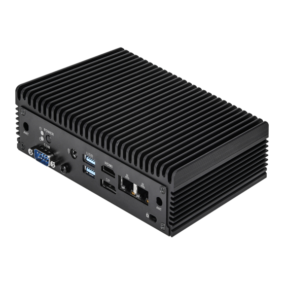
2.2 Rear View Description COM Port Power Button 2 x USB 3.2 Gen2 Ports (Type A) HDMI RJ-45 (2.5G LAN) DC-IN DisplayPort RJ-45 (2.5G LAN) *There are two LEDs on the LAN port. Please refer to the table below for the LAN port LED indications. ACT/LINK LED SPEED LED LAN Port... -
Page 14: Inside View
1300/D4 Series 2.3 Inside View Description SO-DIMM Slots SATA 3.0 Connector M.2 Slot (Key M) M.2 Slot (Key E) Hard disk drive tray (compatible with 2.5" SATA HDD/SSD) SO-DIMM memory, hard drive and mSATA SSD are not included with this system. -
Page 15: Chapter 3 Hardware Installation
Chapter 3 Hardware Installation This chapter helps you install or remove important components. 3.1 How to Remove the Bottom Case 1. Remove the four screws on the bottom case. 2. Then lift up and remove the bottom panel. -
Page 16: How To Install The Wifi Module
1300/D4 Series 3.2 How to Install the WiFi Module 1. Locate the WiFi Module slot on the motherboard. 2. Carefully insert the WiFi Module into the slot. 3. Tighten the screw to secure the WiFi Module to the motherboard. -
Page 17: How To Remove The M.2 Ssd And The Bracket
3.3 How to Remove the M.2 SSD and the Bracket 1. Release the screw and carefully remove the M.2 SSD. 2. Release the screw and remove the bracket from the motherboard. -
Page 18: How To Install The M.2 Ssd
1300/D4 Series 3.4 How to Install the M.2 SSD 1. Locate the M.2 slot on the motherboard. 2. Carefully insert the M.2 SSD into the slot. 3. Tighten the screw to secure the M.2 SSD to the motherboard. -
Page 19: How To Install The 2.5-Inch Hard Drive
3.5 How to Install the 2.5-inch Hard Drive 1. Remove the four screws on the bottom case. Then lift up and remove the bottom panel. 2. Attach the HDD cage to the bottom panel and secure it using the four screws. Then connect the SATA cable to the HDD. - Page 20 1300/D4 Series 3. Connect the SATA Data and Power Cable to the HDD. 4. Connect the SATA Cable to the connector.
- Page 21 5. Then reinstall the bottom panel.
-
Page 22: How To Install The Memory Modules (Ddr4)
1300/D4 Series 3.6 How to Install the Memory Modules (DDR4) 1. The iBOX 1300/D4 Series requires DDR4 SO-DIMM. 2. For dual channel configuration, you always need to install identical (the same brand, speed, size and chip-type) DDR4 SO-DIMM pairs. -
Page 23: How To Install The Vesa Bracket
3.7 How to Install the VESA Bracket 1. Attach the two screws to the base of the iBOX 1300/D4 Series. 2. Attach the VESA Bracket to the rear of a compatible display using the four screws. *Choose mounting holes depending on the mounting hole pattern of your LCD screen... - Page 24 1300/D4 Series 3. Mount the iBOX 1300/D4 Series by sliding it into place.
-
Page 25: How To Install The Wall Mounting Brackets
3.8 How to Install the Wall Mounting Brackets 1. Attach the wall mounting brackets to the base of the iBOX 1300/D4 Series and secure them with screws. 2. The iBOX 1300/D4 Series is installed with the wall mounting brackets. - Page 26 1300/D4 Series Dimension of the iBOX 1300/D4 Series with Wall Mounting Brackets Installed 197.4mm 187.1mm 99.2mm 110.4mm...
-
Page 27: How To Install The Din Rail Mounting Bracket (Optional)
3.9 How to Install the Din Rail Mounting Bracket (Optional) 1. Attach the Din Rail Bracket to the base of the iBOX 1300/D4 Series. 2. Then secure it with screws. Din Rail Bracket is not provided by default. Please purchase it seperately if needed. -
Page 28: Motherboard
1300/D4 Series Chapter 4 Motherboard 4.1 Motherboard Layout AUDIO1 TC_T0 (Type C): BIOS USB4 / Thunderbolt 4 USB3_3_4 (USB3.2 Gen2): Bottom: USB3_3 USB2_7_8 Top: USB3_4 HDMI_DP_1: COM1 Bottom: HDMI Top: DP SATA3_0 USB3_1_2 Industrial (USB3.2 Gen2): Bottom: USB3_1 Top: USB3_2... -
Page 29: Motherboard Specifications
4.2 Motherboard Specifications Form NUC (4.09-in x 4.02-in x 1.5-in, 10.4 cm x 10.2 cm x 3.8 Dimensions Factor Intel® 13th Gen (Raptor Lake-P) Core™ Processors NUC-1360P/D4 (i7-1360P, 4P+8E) NUC-1340P/D4 (i5-1340P, 4P+8E) NUC-1365UE/D4 (i7-1365UE, 2P+8E) Processor NUC-1335UE/D4 (i5-1335UE, 2P+8E) System NUC-1315UE/D4 (i3-1315UE, 2P+4E) NUC-1315U/D4 (i3-1315U, 2P+4E) Chipset... - Page 30 1300/D4 Series 2 x USB 3.2 Gen2 (Type A) 1 x USB4/Thunderbolt™4 (5V/3A, supports DP1.4a display output) *For Thunderbolt support, please refer to Front I/O support list. 1 x USB 3.2 Gen2 (Type-C, 5V/3A, supports DP1.4a display output) Audio 1 (headphone &...
-
Page 31: Onboard Headers And Connectors
4.3 Onboard Headers and Connectors Onboard headers and connectors are NOT jumpers. Do NOT place jumper caps over these headers and connectors. Placing jumper caps over the headers and connectors will cause per- manent damage to the motherboard! USB 2.0 Connector (9-pin USB2_7_8) (see p. - Page 32 1300/D4 Series SATA3 Port (SATA3_0) (see p. 20, No. 5) The Serial ATA3 (SATA3) connector supports SATA data cables for internal storage devices. The current SATA3 interface allows up to 6.0 Gb/s data transfer rate. JP1 Header 1-2: SIO AT Mode...
- Page 33 Back Side : Power Button (PWR_BTN1) Fan Connector +12V (FAN1) FAN_SPEED FAN_SPEED_CONTROL Battery Connector BAT1 BAT1 (BAT1) ESPI Header (ESPI1) ESPI_CLK ESPI_CS# ESPI_RESET# SMB_CLK_MAIN SMB_DATA_MAIN ESPI_IO0 ESPI_IO1 ESPI_IO2 ESPI_IO3 +3VSB GPIO_TEST# ESPI_ALERT#...
-
Page 34: Installation Of Rom Socket
1300/D4 Series 4.4 Installation of ROM Socket * Do not apply force to the actuator cover after IC inserted. * Do not apply force to actuator cover when it is opening over 120 degrees; otherwise, the actuator cover may be broken. -
Page 35: Expansion Slots (M.2 Slots)
4.5 Expansion Slots (M.2 Slots) There are 2 M.2 sockets on this motherboard. M.2 for SSD: 1 x M.2 (KEY M, 2242/2260/2280) with PCIe Gen4 x 4 for SSD. * M.2 Key M 2280 (Supported by bracket) M.2 for Wi-Fi: 1 x M.2 (Key E, 2230) with PCIe x1, USB 2.0 and CNVi for Wireless. M.2 Key-M M.2 Key-E Socket (M2_M1) -
Page 36: Chapter 5 Uefi Setup Utility
Chapter 5 UEFI Setup Utility 5.1 Introduction ASRock Industrial UEFI (Unified Extensible Firmware Interface) is a BIOS utility which offers tweak-friendly options in an advanced viewing interface. The UEFI system works with a USB mouse and offers users a faster, sleeker experience. -
Page 37: Uefi Menu Bar
5.1.2 UEFI Menu Bar The top of the screen has a menu bar with the following selections: Main For setting system time/date information For advanced system configurations Advanced H/W Monitor Displays current hardware status Security For security settings Boot For configuring boot settings and boot priority Exit Exit the current screen or the UEFI Setup Utility Because the UEFI software is constantly being updated, the following UEFI setup... -
Page 38: Navigation Keys
1300/D4 Series 5.1.3 Navigation Keys Use < > key or < > key to choose among the selections on the menu bar, and use < > key or < > key to move the cursor up or down to select items, then press <Enter>... -
Page 39: Main Screen (Advanced Mode)
5.2 Main Screen (Advanced Mode) When you enter the UEFI SETUP UTILITY, the Main screen will appear and display the system overview. Because the UEFI software is constantly being updated, the following UEFI setup screens and descriptions are for reference purpose only, and they may not exactly match what you see on your screen. -
Page 40: Advanced Screen
1300/D4 Series 5.3 Advanced Screen In this section, you may set the configurations for the following items: CPU Configuration, Chipset Configuration, Super IO Configuration, AMT Configura- tion, ACPI Configuration, USB Configuration and Trusted Computing. Setting wrong values in this section may cause the system to malfunction. - Page 41 5.3.1 CPU Configuration Intel Hyper Threading Technology Intel Hyper Threading Technology allows multiple threads to run on each core, so that the overall performance on threaded software is improved. Configuration options: [Enabled] [Disabled] Active Processor P-Cores This allows you to select the number of cores to enable in each processor package. Active Processor E-Cores This allows you to select the number of E-Cores to enable in each processor package.
- Page 42 1300/D4 Series Enhanced Halt State (C1E) The option allows you to enable Enhanced Halt State (C1E) for lower power consumption. Configuration options: [Enabled] [Disabled] Package C State Support The option allows you to enable CPU, PCIe, Memory, Graphics C State Support for power saving.
- Page 43 Intel Turbo Boost Technology Intel Turbo Boost Technology enables the processor to run above its base operating frequency when the operating system requests the highest performance state. The default value is [Enabled]. Configuration options: [Enabled] [Disabled] CPU Thermal Throttling CPU Thermal Throttling allows you to enable CPU internal thermal control mecha- nisms to keep the CPU from overheating.
-
Page 44: Chipset Configuration
1300/D4 Series 5.3.2 Chipset Configuration VT-d Intel® Virtualization Technology for Directed I/O helps your virtual machine monitor better utilize hardware by improving application compatibility and reliability, and providing additional levels of manageability, security, isolation, and I/O performance. Configuration options: [Enabled] [Disabled]... - Page 45 Render Standby Power down the render unit when the GPU is idle for lower power consumption. Configuration options: [Enabled] [Disabled] Onboard LAN1 This allows you to enable or disable the Onboard LAN1 feature. Configuration options: [Enabled] [Disabled] Onboard LAN2 This allows you to enable or disable the Onboard LAN2 feature. Configuration options: [Enabled] [Disabled] Onboard HD Audio This allows you to enable or disable the onboard HD audio.
-
Page 46: Storage Configuration
1300/D4 Series 5.3.3 Storage Configuration SATA Controller(s) The option allows you to enable or disable the SATA controllers. Configuration options: [Enabled] [Disabled] SATA Mode Selection AHCI supports new features that improve performance. Configuration option: [AHCI] AHCI (Advanced Host Controller Interface) supports NCQ and other new features that will improve SATA disk performance. - Page 47 SATA Aggressive Link Power Management SATA Aggressive Link Power Management allows SATA devices to enter a low power state during periods of inactivity to save power. It is supported only by AHCI mode. Configuration options: [Enabled] [Disabled] Hard Disk S.M.A.R.T. S.M.A.R.T stands for Self-Monitoring, Analysis, and Reporting Technology.
-
Page 48: Super Io Configuration
1300/D4 Series 5.3.4 Super IO Configuration COM1 Configuration Use this to set parameters of COM1. Type Select Use this to select COM1 port type: [RS232], [RS422] or [RS485]. WDT Timeout Reset Use this to set the Watch Dog Timer. -
Page 49: Amt Configuration
5.3.5 AMT Configuration USB Provisioning of AMT Use this to enable or disable AMT USB Provisioning. The default is [Disabled]. MAC Pass Through The option enables or disables MAC Pass Through function. Dynamic Lan Switch This allows switching AMT support from Integrated LAN to Discrete LAN. Activate Remote Assistance Process Trigger CIRA boot. - Page 50 1300/D4 Series One Click Recovery(OCR) Configuration Configuration setting for One Click Recovery. This allows access for AMT to boot a recovery OS application Remote Platform Erase Configuration Remote Platform Erase configuration menu. MEBx This Formset contains forms for configuring MEBx.
-
Page 51: Acpi Configuration
5.3.6 ACPI Configuration Suspend to RAM Suspend to RAM allows you to select [Disabled] for ACPI suspend type S1. It is recommended to select [Auto] for ACPI S3 power saving. Configuration options: [Auto] [Disabled] Onboard LAN Power On Use this item to enable or disable onboard LAN to turn on the system from the power-soft-off mode. -
Page 52: Usb Configuration
1300/D4 Series 5.3.7 USB Configuration USB Power Control Use this option to control USB power. Configuration options: [Always Enabled] [Default Setting]... -
Page 53: Trusted Computing
5.3.8 Trusted Computing NOTE: Options vary depending on the version of your connected TPM module. Security Device Support Security Device Support allows you to enable or disable BIOS support for security device. O.S. will not show Security Device. TCG EFI protocol and INT1A interface will not be available. - Page 54 1300/D4 Series Pending Operation Pending Operation allows you to schedule an Operation for the Security Device. NOTE: Your computer will reboot during restart in order to change State of the Device. Configuration options: [None] [TPM Clear] Platform Hierarchy This item allows you to enable or disable Platform Hierarchy.
- Page 55 Device Select This item allows you to select the TPM device to be supported. [TPM 1.2] restricts support to TPM 1.2 devices. [TPM 2.0] restricts support to TPM 2.0 devices. [Auto] supports both TPM 1.2 and TPM 2.0 devices with the default set to TPM 2.0 devices.
-
Page 56: Hardware Health Event Monitoring Screen
1300/D4 Series 5.4 Hardware Health Event Monitoring Screen This section allows you to monitor the status of the hardware on your system, including the parameters of the CPU temperature, motherboard temperature, fan speed, chassis fan speed, and the critical voltage. -
Page 57: Security Screen
5.5 Security Screen In this section you may set or change the supervisor/user password for the system. You may also clear the user password. Supervisor Password Set or change the password for the administrator account. Only the administrator has the authority to change the settings in the UEFI Setup Utility. Leave it blank and press enter to remove the password. -
Page 58: Boot Screen
1300/D4 Series 5.6 Boot Screen This section displays the available devices on your system for you to configure the boot settings and the boot priority. Boot Option #1 The item allows you to set the system boot order. Boot From Onboard LAN The item allows the system to be waked up by the onboard LAN. - Page 59 Full Screen Logo [Enabled] Select this item to display the boot logo. [Disabled] Select this item to show normal POST messages.
-
Page 60: Exit Screen
1300/D4 Series 5.7 Exit Screen Save Changes and Exit When you select this option, the following message “Save configuration changes and exit setup?” will pop out. Select [Yes] to save the changes and exit the UEFI SETUP UTILITY. Discard Changes and Exit When you select this option, the following message “Discard changes and exit... - Page 61 Chapter 6 Software Support 6.1 Install Operating System ® ® This motherboard supports various Microsoft Windows operating systems: 11 64-bit / 10 64-bit. Because motherboard settings and hardware options vary, use the setup procedures in this chapter for general reference only. Refer your OS docu- mentation for more information.
Need help?
Do you have a question about the iBOX 1300/D4 Series and is the answer not in the manual?
Questions and answers