Table of Contents
Advertisement
Quick Links
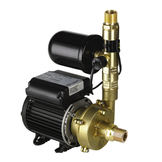
STUART
Installation, Operation & Maintenance
Instructions
Please leave this instruction booklet with the home owner as it contains
important guarantee, maintenance and safety information
Read this manual carefully before commencing installation.
This manual covers the following products:
CH 12-14 B
Pt. No. 46349
50 Hz
2
CE compliant product
Advertisement
Table of Contents

Related Manuals for Stuart Turner CH 12-14 B


Summary of Contents for Stuart Turner CH 12-14 B
- Page 1 Please leave this instruction booklet with the home owner as it contains important guarantee, maintenance and safety information Read this manual carefully before commencing installation. This manual covers the following products: CH 12-14 B Pt. No. 46349 50 Hz CE compliant product...
-
Page 2: Table Of Contents
Other clean non aggressive, non explosive liquids with similar characteristics to water may be pumped, consult Stuart Turner for such applications. STORAGE If this product is not to be installed immediately on receipt, ensure that it is stored in a dry, frost and vibration free location in its original packaging. - Page 3 This product should not be used for the supply of water to more than one dwelling (house, apartment, flat). Maximum head (closed valve) CH 12-14 B-14 metres. The motor casing can become very hot under normal operating conditions. Care must be taken to ensure it cannot be touched during operation.
- Page 4 If the supply cord is to be changed or is damaged, it must be replaced with a special cord assembly available from Stuart Turner or one of their approved repairers. Please read installation details carefully as they are intended to ensure this product provides long, trouble free service.
-
Page 5: Checklist
(1 “ BSP) adaptor or fitting. IMPORTANT: With the pump removed from its packaging check for any damage prior to installation. If any damage is found contact Stuart Turner Ltd within 24 hours of receipt. 28 mm copper inlet pipework (suction). -
Page 6: Pre-Installation Assembly
PRE-INSTALLATION ASSEMBLY Pressure Check and Assembly of Pressure Vessel a) Certain models are supplied in two parts, the main pump and the pressure vessel. The pressure vessel is pre-charged with air at the factory (see table below). This pressure should be checked at the Schrader valve (Fig. 2) using a tyre pressure gauge and adjusted if necessary using a car or bicycle pump prior to installation. - Page 7 Re-positioning of Pressure Vessel The pressure vessel can be rotated to alternative positions (Fig. 4) in the event of the factory fitted position being unsuitable for a specific installation. a) Remove pressure vessel by unscrewing anti-clockwise. b) Using a 2 mm allen key, carefully loosen all three retaining grub screws by two turns (Fig.
-
Page 8: Important Facts - Read Before Commencing Installation
1 IMPORTANT FACTS: READ BEFORE COMMENCING PUMP INSTALLATION A Water storage capacity. 1.11 The hot and cold water storage capacity must be sufficient to meet the flow rates required by the pumped equipment and any other water using fittings and appliances, which may be operated simultaneously. 1.12 Ensure the pump is primed as described in the priming section before starting, damage to the shaft seal will result otherwise. -
Page 9: Location
2.22 Direction of flow: Ensure the water flow is in the direction of the arrow that is marked on the flow switch reed clamp (vertically upwards). 2.23 Flexible hoses: Only use the Stuart Turner hose set supplied with the pump. 2.24 Isolating valves: Separate isolating valves (non restrictive) must be fitted to allow easy pump service. - Page 10 2 LOCATION - COLD WATER INSTALLATION Cold water pump Fig. 5 2.26 The cold water supply: The supply must be AIR FREE and have a DEDICATED CONNECTION to the tank which should be via a tank connector, positioned at a slightly lower level (25 mm minimum) than the feed pipe to the hot water cylinder.
- Page 11 2.30 The pumps can be used in a suction lift installation providing the height of lift is within the limits specified in the limits of application section and the liquid to be pumped is cold water (for applications other than cold water contact Stuart Turner). Cont ... - 11 -...
- Page 12 2.31 Before deciding where to locate the unit, check to ensure the static outlet head (Fig. 8) does not exceed the maximum requirements of 6 metres. 2.32 A footvalve and strainer must always be used and the suction pipework size must match the pump.
-
Page 13: Pump Connections
3 PUMP CONNECTIONS 3.11 Hose to pump: These pumps have G 1 threaded connections to accept the hoses supplied. The hose end is made water tight with a sealing washer on assembly, nip tight to 4/5 Nm for water tight seal (Do not overtighten). 3.12 Hose to pipework: Hoses terminating in G 1 threaded connections are supplied and when securing the male end to a suitable pipe fitting, seal with PTFE tape or other suitable sealant. -
Page 14: Electrical Installation
4 ELECTRICAL INSTALLATION 4.11 Regulations: The electrical installation must be carried out in accordance with the current national electrical regulations and installed by a qualified person. 4.12 Safety: In the interests of electrical safety a 30 mA residual current device (R.C.D. not supplied) should be installed in the supply circuit. This may be part of a consumer unit or a separate unit. - Page 15 The wire which is coloured blue must be connected to the terminal which is marked with the letter N or coloured black. The wire which is coloured brown must be connected to the terminal which is marked with the letter L or coloured red. 4.22 Wiring Diagram: MAIN WINDING BLUE...
- Page 16 4.26 Supply Cord Extension: The pumps are fitted with a supply cord to the following specifications:- All models:- ....HO5VV-F3 G 0.75 mm² - 6 Amp rating. If the supply cord is to be extended, a cord of the same specification should be used.
-
Page 17: Commissioning
5 COMMISSIONING 5.11 System Flushing: This pump-set incorporates plastic components that must not come into contact with solder flux, acid-based descalents or aggressive cleaning agents. The pipework system should be flushed out prior to the pump being connected to ensure any contaminants/chemical residues and foreign bodies are removed from elsewhere in the system. - Page 18 Carefully check pump and pipework for leaks whilst pump running and stationary before leaving the installation unattended. 5.15 For further technical support: Phone the Stuart Turner TechAssist team on +44 (0) 800 31 969 80. Our staff are trained to help and advise you over the phone.
-
Page 19: Maintenance
6 MAINTENANCE 6.11 Disconnect electrical supply before working on pump. 6.12 Turn off liquid supplies to the pump and release pressure by opening liquid outlets before attempting maintenance. 6.13 Inlet strainer: Incorporated in the strainer is a removable gauze filter which may require periodic cleaning. - Page 20 Air Charge Model bar (psi) All models 0.9 (13) ‘O’-Ring Schrader valve (under cap) Pressure vessel Detail view of ‘O’-Ring ‘O’-Ring groove Note: This image is for in fitting point Fitting point reference only. Fig. 15 NOTE: Do not over tighten pressure vessel. 6.15 Water scale: As water is heated scale deposits are released in areas of hard water, scale can cause the mechanical seal to stick if left without use for long periods.
-
Page 21: Technical Specification
7 TECHNICAL SPECIFICATION CH 12-14 B Pump Model 50 Hz 46349 General Guarantee 2 years WRAS approval 1709116 Approvals WRAS, CE Pump type Centrifugal single stage Features Pump control Pressure/flow switch Anti-vibration feet ü Inlet strainer(s) ü Flexible hoses Run on Timer... - Page 22 338 mm Weight - including fittings 8.7 Kg Stuart Turner reserve the right to amend the specification in line with its policy of continuous development of its products. *Note: The maximum pressure that can be applied to the pump under any installation conditions.
-
Page 23: Trouble Shooting
If pump continues to run, this indicates a closed circuit in or pressure switch. either the flow switch reed, pressure switch or P.C.B. in the terminal box. Contact Stuart Turner. Jammed flow switch. Remove outlet hoses and check that flow switch sits in lowest position. - Page 24 8.11 Dry Run Protection: This pump is fitted with a safety control circuit, which will detect the following fault condition: Dry running caused by water starvation to the pump. Should the pump run out of water it will stop as part of a “protective logic sequence”, detailed below.
- Page 25 If this does not happen, this indicates a possible fault with the reed switch or the P.C.B which is located within the terminal box. These should be checked electrically. Consult Stuart Turner for further instructions. 8.15 Environment Protection: Your appliance contains valuable materials which can be recovered or recycled.
-
Page 26: Guarantee
We are confident this pump will provide many years of trouble free service as all our products are manufactured to the very highest standard. All CH 12-14 B pumps are guaranteed to be free from defects in materials or workmanship for 2 years from the date of purchase. - Page 27 NOTES Cont ... - 27 -...
- Page 28 Signed ..........Stuart Turner are an approved company to BS EN ISO 9001:2015...
Need help?
Do you have a question about the CH 12-14 B and is the answer not in the manual?
Questions and answers