Regin Optigo OP5U Manual
Hide thumbs
Also See for Optigo OP5U:
- Instructions manual (14 pages) ,
- Instructions manual (14 pages) ,
- Instruction manual (14 pages)

Related Manuals for Regin Optigo OP5U


Summary of Contents for Regin Optigo OP5U
- Page 1 O P T I G O – R E A D Y - S T E A D Y - G O Optigo OP5U Manual ©Copyright AB Regin, Sweden, 2012...
- Page 2 The software described in this document is supplied under license by Regin and may be used or copied only in accordance with the terms of the license. No part of this document may be reproduced or transmitted in any form, in any fashion, electronically or mechanically, without the express, written permission of Regin.
-
Page 3: Installation
Table of contents Chapter 1 About this manual More information Chapter 2 Introduction to Optigo Optigo controllers Optigo OP5U Chapter 3 Technical data Chapter 4 Installation and wiring Installation Wiring Supply voltage Inputs and outputs Chapter 5 Control modes Control mode 1, Temperature control... - Page 4 Reset to factory setting Chapter 9 Index...
- Page 5 Chapter 1 About this manual This manual describes the controller Optigo OP5U. It is applicable to program revisions from R19. More information More information on OP5U can be found in: Optigo controllers – Sales brochure for Optigo controllers ...
-
Page 6: Mounting
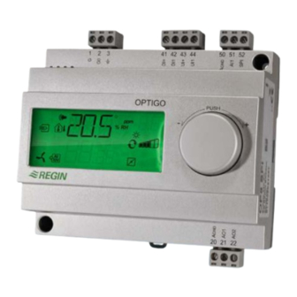
Optigo OP10 manual. Mounting Optigo is designed primarily for DIN-rail mounting but can also be screw-mounted to any suitable surface. The controller is intended for stationary indoor use. Optigo OP5U user manual Chapter 2 Introduction to Optigo... - Page 7 Optigo OP5U Optigo OP5U is a pre-programmed, configurable controller. It has been designed with the main intention of replacing a number of Regin’s Aqualine controllers. All configuration and normal handling is done using the display and the knob on the front.
-
Page 8: Supply Voltage
AO1 ..............0…10 V DC; 8 bit D/A short-circuit protected AO2 ..............0…10 V DC; 8 bit D/A short-circuit protected Agnd ................... Signal neutral for analogue outputs Other data Display ..............Numeric / graphic. Background illumination Optigo OP5U user manual Chapter 3 Technical data... - Page 9 Humidity sensor (can be used for general control (3)) ... HRT, HRT250, HDT3200, HDT2200 Pressure sensor ............. DMD, DTL-series, DTK-series, TTK-series The accessories are available from Regin. For more detailed information, see product sheets and instructions which are available at www.regin.se.
- Page 10 Supply voltage 24 V AC ±15%, 50…60 Hz. 3 VA If the Optigo OP5U and active sensors and actuators connected to it share transformer, it is essential that the same transformer-pole is used as reference for all the equipment. Failure to do so will prevent the equipment from functioning as intended and may also lead to damages.
-
Page 11: Analogue Inputs
Analogue outputs must refer to a A terminal or directly to G0. If the Optigo OP5U and active sensors and actuators connected to it share transformer, it is essential that the same transformer-pole is used as reference for all the equipment. Failure to do so will prevent the equipment from functioning as intended and may also lead to damages. -
Page 12: Control Modes
The pressure at the sensor is kept at the setpoint value by controlling the output signal on AO1. The AO1 inverted signal is received from AO2. The setpoint is automatically adjusted according to the outdoor temperature. A single PI control loop is used. Optigo OP5U user manual Chapter 5 Control modes... - Page 13 When the start signal is deactivated the controller will set the outputs to 0. Note: This input must always be wired since it controls the starting and stopping of normal control. Optigo OP5U user manual Chapter 5 Control modes...
- Page 14 TG-R4/PT1000 or TBI-PT1000. The setpoint device is connected between terminal 52 SPI and the reference for the analogue inputs, A . For more information on configuration and setpoint reading, see chapters 7 and 8. Wiring example: Heating / cooling with change-over function Optigo OP5U user manual Chapter 5 Control modes...
-
Page 15: Control Mode 2
0. Note: This input must always be wired since it controls the starting and stopping of normal control. Wiring example: CO2-control using damper or frequency converter Optigo OP5U user manual Chapter 5 Control modes... -
Page 16: Control Mode 3
DI1. The humidistat should be normally closed. Opening of the contact when the humidity rises above the set maximum value will force the humidity output to 0. Wiring example: Combined humidification / dehumidification Optigo OP5U user manual Chapter 5 Control modes... -
Page 17: Control Mode 4
0. Note: This input must always be wired since it controls the starting and stopping of normal control. Wiring example. Pressure control Optigo OP5U user manual Chapter 5 Control modes... -
Page 18: Compensation Of The Pressure Setpoint
0. Note: This input must always be wired since it controls the starting and stopping of normal control. Wiring example: Outdoor temperature compensated pressure control Optigo OP5U user manual Chapter 5 Control modes... -
Page 19: Inputs And Outputs
To exit this menu again, click on the knob and then twist the knob clockwise and you will be returned to the Base display. Setpoint When in the Base Display, a click on the encoder button gives direct access to the Setpoint menu. See chapter 7 Setpoint. Optigo OP5U user manual Chapter 6 Display and encoder... - Page 20 10 seconds. The 10-second level holds all the configuration menus. See chapter 8 Configuration. Note: The controller must display the Base Display when pressing the encoder knob to reach the 10-second level. Display symbols Optigo OP5U user manual Chapter 6 Display and encoder...
- Page 21 External setpoint can be used for control mode 1. The SPI input can also be read via the I/O menu. The temperature range for an external setpoint device is 0…40°C. Optigo OP5U user manual Chapter 7 Setpoint...
- Page 22 For temperature control there is a choice of 8 different output signal combinations. Select one fitting the application on hand. Output Graphic symbol symbol 1. Heating 2. Cooling 3. Heating Cooling 4. Heating Heating 5. Cooling Cooling 6. Heating Damper 7. Cooling Damper 8. Change-over / Optigo OP5U user manual Chapter 8 Configuration...
- Page 23 In two control modes involving diverging output signals (heating – cooling or general control) you can set a neutral zone between the outputs. The setpoint will be placed at the middle of the neutral zone. Optigo OP5U user manual Chapter 8 Configuration...
- Page 24 The output can be min./max. limited. The minimum value can be set between 0…99% and the maximum value between 1…100%. If min./max. parameters are accidentally set to overlap one another, the max. function will be disabled and the output will assume control. Optigo OP5U user manual Chapter 8 Configuration...
- Page 25 Outdoor temp -20°C 10°C Example: With an ordinary setpoint of 300 Pa, a starting point S.P of +10°C and a SPL of 200 Pa at -20°C you get the following setpoint-to-outdoor temperature relation Optigo OP5U user manual Chapter 8 Configuration...
- Page 26 The OP5U can be reset to factory settings by configuring general control (mode 3) and setting the transmitter range to 100% and the P-band to 99. Then cut the power supply. When power is reapplied all configuration settings will be reset to factory setting. Optigo OP5U user manual Chapter 8 Configuration...
-
Page 27: Table Of Contents
Control mode 3 ..............16 Control mode 4 ..............17 I Control mode 5 ..............18 general ................10 Inputs and outputs ............7, 11 Analogue inputs .............. 11 Analogue outputs ............11 Optigo OP5U user manual Chapter 9 Index... - Page 28 Germany France Spain Singapore Hong Kong Regin Controls RICCIUS + SOHN GmbH Regin Controls SARL Regin Ibérica, S.A. Regin Controls Asia Pacific Pte Ltd Hong Kong Ltd Haynauer Str. 49 32 rue Delizy C/Arganda 18 local 66 Tannery Lane...
Need help?
Do you have a question about the Optigo OP5U and is the answer not in the manual?
Questions and answers