Advertisement
Available languages
Available languages
Quick Links
Download this manual
See also:
Manual
INSTRUCTION
EN
OPTIGO OP5
i
Read this instruction before installation
and wiring of the product
Consult documentation in all cases where this symbol
is used, in order to find out the nature of the potential
hazards and any actions to be taken
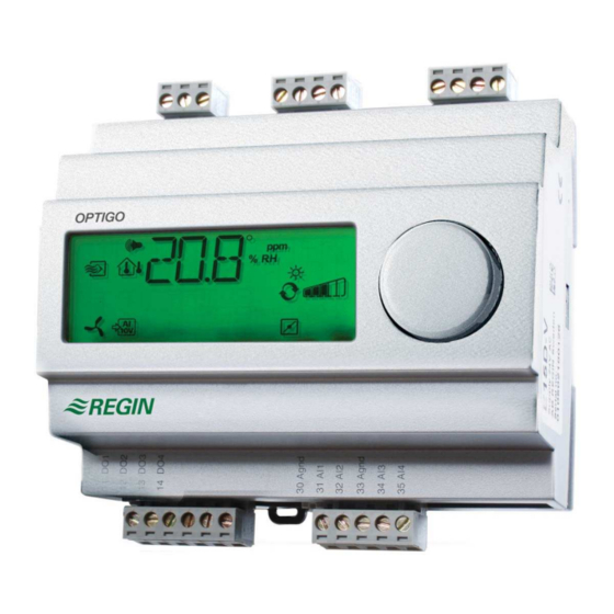
Controller with display
Optigo OP5 is a pre-programmed, configurable controller. It has 5
inputs/outputs and can be configured to control temperature, CO
humidity or pressure. All configuration and normal handling is done
using the display and the knob on the front. From revision R18, it is
possible to connect an external PT1000 setpoint device.
Technical data
Supply voltage
24 V AC ±15%, 50/60 Hz
Power consumption
3 VA
Ambient temperature
0...50°C
Ambient humidity
Max. 90% RH
Storage temperature
-20...70°C
Display
Numeric / graphic. Background
illumination.
Inputs/outputs
Refer to connection illustrations and
table below
Terminal blocks
Disconnectable, so-called lift type for
cable cross-section max 2.5 mm
Protection class
IP20
Material, casing
Polycarbonate, PC
Weight
215 g incl. terminal blocks
Dimensions
122 x 120 x 64 mm (WxHxD incl. terminals,
fixed installation)
Pollution degree
2
Temperature settings
Temperature, supply air
-20...40°C
External setpoint
0...40°C
Neutral zone
0...10°C
P-band
0...99°C
I-time
0...990 s
Min limit damper
0...99
Other settings
Setpoint values
CO
0...100% of max set value on UI1
2
Humidity (RH)
0...100% of max set value on UI1
Pressure (Pa)
0...100% of max set value on UI1
10 V DC in on UI1
CO
0...9900 ppm
2
Humidity
0...100% RH
Pressure
0 Pa...500 kPa
Neutral zone
10% of max
P-band
CO
0...100% of UI1
2
Humidity (RH)
0...100% of UI1
Pressure (Pa)
0...300% of UI1
I-time
0...990 s
Outdoor compens. start
-30...50°C
,
Pressure at -20°C
2
outdoor temp.
0 Pa...500 kPa
Installation
OP5 must be mounted in a DIN-standard casing (minimum 7 modules) or
in a cabinet, either on a DIN-rail or, using the two screw-pockets provided,
by being screwed to any suitable flat surface in the cabinet. The control-
ler can also be mounted in a cabinet door or other control panel, using a
suitable front-mounting kit.
The controller must be connected to a 24 V safety insulating transformer
providing mains insulation.
OPTIGO OP5
Follow table 1 below for connection.
Table 1. I/O connection terminals. Terminals 2, 20 and 50 are internally con-
2
nected.
Terminal
Designation
1
G
2
G0
3
20
AGnd
21
AO1
22
AO2
41
DI+
42
DI1
43
UI+
44
UI1
50
AGnd
51
AI1
52
SPI
Digital inputs DI and UI are only intended to be used with a
potential-free contact or switch. If the Optigo OP5 and active sensors
and actuators connected to it share transformer, it is essential that
the same transformer-pole is used as reference for all the equipment.
Failure to do so will prevent the equipment from functioning as
intended and may also lead to damages.
For best protection against disturbances, a shielded twisted-pair cable
should be used for wiring the sensors. Ground the shield at one end.
The protection provided by the equipment may be impaired by im-
proper use.
Operation
Supply voltage 24 V AC
Ref. for AO1 and AO2
0...10 V DC Output
0...10 V DC Output
Reference for DI1
Digital input
Reference for UI1 digital mode
0...10 V DC or Digital input
Ref. for AI1 and UI1 analogue
PT1000 temp. sensor input
Input PT1000 setpoint device
1
Advertisement

Related Manuals for Regin OPTIGO OP5


Summary of Contents for Regin OPTIGO OP5
- Page 1 Digital inputs DI and UI are only intended to be used with a and wiring of the product 10 V DC in on UI1 potential-free contact or switch. If the Optigo OP5 and active sensors 0...9900 ppm and actuators connected to it share transformer, it is essential that Humidity 0...100% RH...
-
Page 2: Control Modes
10 seconds. The 10-second level holds all the configuration menus. Note: The controller must display the Base Display when pressing the encoder knob to reach the 10-second level. OPTIGO OP5... - Page 3 The calculated setpoint is displayed by turning See the “Optigo OP5 Manual” for more information about the sation the knob clockwise when in the Base Display. configuration menus in the 10-second level. The manual can be down- loaded from www.regin.se.
- Page 4 Tryck vid -20°C utetemp. 0 Pa...500 kPa Reset to factory setting Optigo OP5 är en förprogrammerad, konfigurerbar regulator. Den har 5 OP5 can be reset to factory settings by configuring Humidity control Installation ingångar/utgångar och kan konfigureras till att styra temperatur, CO...
- Page 5 Om Optigo OP5 och de aktiva givare och ställdon som kopplas till den -reglering Tryckreglering delar transformator, är det nödvändigt att samma transformatorpol -värdet vid givaren hålls till börvärdet genom reglering av Trycket vid givaren hålls till börvärdet genom reglering av används som referenspol till all utrustning.
- Page 6 är beroende av utetemperaturen. konfigureringsnivån. Genom att vrida ratten medurs när man befinner sig i Grunddisplayen visas det beräknade börvärdet. Se “Optigo OP5 Manual” för mer information om konfigurerings- Utgångs- menyerna i 10-sekundersnivån. Manualen kan laddas ner från punkt för www.regin.se.
-
Page 7: Återställning Till Fabriksinställning
Produkten uppfyller kraven för gällande europeiska LVD-standard IEC EN 61010-1. Teknisk support Teknisk hjälp och råd på telefon: 031 720 02 30 Kontakt AB Regin, Box 116, 428 22 Kållered Tel: +46 31 720 02 00, Fax: +46 31 720 02 50 www.regin.se, info@regin.se OPTIGO OP5... - Page 8 10 V DC en entrée sur UI1 Les entrées digitales DI et UI ne doivent être raccordées qu’à 0...9 900 ppm des contacts libres de potentiel. Si l’Optigo OP5, les sondes et autres Humidité 0...100 %HR organes de commande associés (actionneurs) sont alimentés par le Veuillez lire cette instruction avant de procéder à...
- Page 9 Pour naviguer dans les menus Lorsque vous êtes au niveau 0, vous pouvez choisir le mode de tournez le bouton et appuyez pour valider votre choix. contrôle. Appuyez sur le bouton et vérifiez que l’icône indiquant que OPTIGO OP5...
- Page 10 Directive basse tension 2006/95/EC Ce produit est conforme aux exigences de la directive BT et répond à Voir le manuel «Optigo OP5 - Manuel» pour en savoir plus sur les la norme EN61010-1. menus de configuration. Le manuel peut être téléchargé depuis le site de Regin : www.regin.fr.
- Page 11 Die digitalen Eingänge DI und UI sind nur für potentialfreie Druck (Pa) 0...100 % des Maximalwerts von UI1 Kontakte oder Schalter vorgesehen. Werden der Optigo OP5 und die 10 V DC Eing. an UI1 angeschlossenen aktiven Sensoren und Stellantriebe vom gleichen Diese Montageanleitung vor Installation und Anschluss 0...9900 ppm...
- Page 12 Entfeuchtung. Ein einfacher PI Regelkreis wird verwendet. fühler Falls die relative Feuchte auf einen Maximalwert begrenzt Abbildung 5. Klemmenbelegungsbeispiel: Außentemperaturgeführte werden soll, ist ein HMH Hygrostat in Reihe mit dem Startsignal Druckregelung an die Klemmen 41 und 42 anzuschließen. Das Display-Menüsystem OPTIGO OP5...
- Page 13 Alle Konfigurationseinstellungen sind nach dem Anklicken des Drehknopfes gültig. Sie werden aber erst dann in den Flashspeicher AB Regin, Box 116, SE-428 22 Kållered, Schweden Tel: +46 31 720 übertragen, wenn die Konfigurationsebene über das OK-Menü oder 02 00, Fax: +46 31 720 02 50 wegen Inaktivität verlassen wird.
Need help?
Do you have a question about the OPTIGO OP5 and is the answer not in the manual?
Questions and answers