Advertisement
Available languages
Available languages
Quick Links
INSTRUCTION
EN
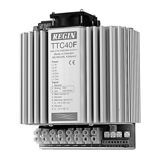
TTC40F
i
Read this instruction before installation
and wiring of the product
Consult documentation in all cases where this symbol
is used, in order to find out the nature of the potential
hazards and any actions to be taken
Triac controller for proportional control
of electric heating
TTC40F is a proportional controller for electric heating with automatic
voltage adaption. TTC40F pulses the whole load On - Off. The ratio
between On-time and Off-time is varied 0 - 100% to suit the prevailing
heat demand. The current is always switched at zero phase angle to
prevent RFI.
TTC40F can control both symmetrical Y-connected 3-phase heaters
and symmetrical or asymmetrical Delta-connected heaters.
TTC40F is only intended for electric heating control. The control prin-
ciple makes it unsuitable for motor- or lighting control.
TTC40F is intended for DIN-rail mounting.
Installation
Mount TTC40F on a DIN-rail in a cabinet or other enclosure.
Mount TTC40F vertically with the text right side up.
Protection class:
IP20.
Ambient temperature:
0 - 40°C
N.B. TTC40F emits approx. 70W of heat at full output which must be
dissipated.
Wiring
Supply voltage
Terminals L1in, L2in and L3in.
Supply voltage:
210-255 or 380-415V AC
3 phase, 50 - 60 Hz with automatic voltage adaption.
Maximum current 40A/phase.
N.B. The supply voltage to TTC40F should be wired via an all-pole switch
with a minimum contact gap of 3mm.
N.B. TTC40F must be earthed.
1
2 3 4 5 6 7 8 9
L1 L2 L3 L3 L2 L1
1 1
3
Figure 1: Wiring of supply voltage and load
Load
Terminals L1out, L2out and L3out.
Resistive 3-phase heater without neutral
Maximum load:
5290W/phase at 230V phase - phase voltage (40A).
9200W/phase at 400V phase - phase voltage (40A).
Minimum load:
530W/phase at 230V phase - phase voltage (4A).
920W/phase at 400V phase - phase voltage (4A).
Main sensor and external set-point (figs 2-6)
Terminals 1and 4. Low voltage. Not polarity sensitive.
N.B. Terminals 2 and 3 are internally connected and are used to simplify
wiring when using external setpoint.
N.B. Choice of internal or external setpoint is done using switch 1.
TTC40F
Figure 2: Wiring of room sensor TG-R530 or TG-R6xx when using
internal setpoint
Figure 3: Wiring of room sensor TG-R430 used as external
setpoint and sensor
1 2
3 4
TG-K3xx
TG-G1xx
Figure 4: Wiring of floor or duct sensor when using
internal setpoint
TG-K3xx
1 2
3 4
TG-R4xx
TG-G1xx
2
3
Figure 5: Wiring of external separate sensor when using TG-R4xx
as external setpoint
TG-K3xx
1 2
3 4
TBI-xx
TG-G1xx
1
2
Figure 6: Wiring of external, separate sensor when using
potentiometer TBI-xx as external setpoint
1
Advertisement

Related Manuals for Regin TTC40F


Summary of Contents for Regin TTC40F
- Page 1 Mount TTC40F vertically with the text right side up. Protection class: IP20. Ambient temperature: 0 - 40°C N.B. TTC40F emits approx. 70W of heat at full output which must be dissipated. Figure 2: Wiring of room sensor TG-R530 or TG-R6xx when using internal setpoint Wiring Supply voltage Terminals L1in, L2in and L3in.
-
Page 2: Control Principle
Terminals 5 and 7. Low voltage. Not polarity sensitive. downward position. Switch the voltage on. TTC40F can also be run against a 0 - 10V DC control signal from another When running room temperature control the supply air temperature TTC40F should give full uninterrupted power and the LED controller. -
Page 3: Installation
0 - 40°C. Icke kondenserande sas. Begränsningsgivaren placeras i tilluftkanalen efter värmaren. R6xx vid drift med internt börvärde OBS: TTC40F avger vid full effekt c:a 70W förlustvärme som måste Önskad funktion ställs in med hjälp av funktionsomkopplare 2 och 3. kunna kylas bort. - Page 4 (då ärvärdet = börvärdet) kommer lysdioden att blinka i takt med att RoHS OBS: Min och max-begränsningsfunktionerna kan användas samti- TTC40F pulsar fram ström. Pulscykeltiden är 6 - 60 sek beroende på Produkten uppfyller Europaparlamentets och rådets direktiv 2011/65/ digt eller var för sig.
- Page 5 920 W/Phase bei 400 V Hauptspannung (4 A) TBI-xx TG-G1xx nach unten hin begrenzt werden. TTC40F kann für die Steuerung sowohl symmetrischer Heizregistern in Sternschaltung als auch sym- Hauptfühler und ext. Sollwert (Abb. 2...6) metrischer oder asymmetrischer Heizregistern in Dreieckschaltung Klemme 1 und 4.
- Page 6 Externes Steuersignal Haynauer Str. 49, 12249 Berlin stellen. Die Versorgungs-spannung einschalten. TTC40F muß die TTC40F kann auch für die Steuerung mit einem externen 0...10V DC Tel: +49 30 77 99 40 gesamte Leistung ohne Unterbrechung abgeben, und die Diode muß...
- Page 7 N.B. Choisir le point de consigne interne ou externe avec l’interrupteur 1. potentiomètre TBI-xx comme réglage de consigne Montez le TTC40F sur rail DIN, dans une armoire ou dans un autre recouvrement. Monter à la verticale avec le texte à l’endroit.
- Page 8 Vérifier si les bornes L1in, L2in et L3in sont sous tension et revérifier les positions des sélecteurs de sonde. Si cela est OK, TTC40F a probablement un défaut. Si le LED est allumé mais il n’y a pas de courant: Vérifier la résistance du réchauffeur. Si cela est OK, TTC40F a probablement un défaut.
Need help?
Do you have a question about the TTC40F and is the answer not in the manual?
Questions and answers