Table of Contents
Advertisement
Available languages
Available languages
Quick Links
INSTRUCTION
EN
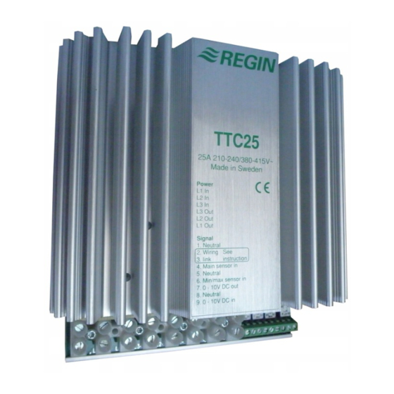
TTC25
i
Read this instruction before installation
and wiring of the product
Consult documentation in all cases where this symbol
is used, in order to find out the nature of the potential
hazards and any actions to be taken
Triac controller for proportional control
of electric heating
TTC25 is a proportional controller for electric heating with automatic
voltage adaption. TTC25 pulses the whole load On - Off. The ratio
between On-time and Off-time is varied 0 - 100% to suit the prevailing
heat demand. The current is always switched at zero phase angle to
prevent RFI.
TTC25 can control both symmetrical Y-connected 3-phase heaters
and symmetrical or asymmetrical Delta-connected heaters.
TTC25 is only intended for electric heating control. The control
principle makes it unsuitable for motor- or lighting control.
TTC25 is intended for DIN-rail mounting.
Mount TTC25 on a DIN-rail in a cabinet or other enclosure.
Mount TTC25 vertically with the text right side up.
Protection class:
IP20.
Ambien temperature:
0 - 40°C
N.B. TTC25 emits approx. 45W of heat at full output which must be
dissipated.
Wiring
Supply voltage
Terminals L1in, L2in and L3in.
Supply voltage:
210-255 or 380-415V AC
3 phase, 50 - 60 Hz with automatic voltage adaption.
Maximum current 25A/phase.
N.B. The supply voltage to TTC25 should be wired via an all-pole switch
with a minimum contact gap of 3mm.
N.B. TTC25 must be earthed.
1
2 3 4 5 6 7 8 9
L1 L2 L3 L3 L2 L1
1 1
3
Figure 1: Wiring of supply voltage and load
Load
Terminals L1out, L2out and L3out.
Resistive 3-phase heater without neutral.
Maximum load:
3300W/phase at 230V phase - phase voltage (25A).
5750W/phase at 400V phase - phase voltage (25A).
Minimum load:
530W/phase at 230V phase - phase voltage (4A).
920W/phase at 400V phase - phase voltage (4A).
Main sensor and external setpoint (figs 2-6)
Terminals 1 and 4. Low voltage. Not polarity sensitive.
N.B. Terminals 2 and 3 are internally connected and are used to simplify
wiring when using external setpoint.
N.B. Choice of internal or external setpoint is made using switch 1.
TTC25
TG-R5xx
1 2
3 4
TG-R3xx
1
2
Figure 2: Wiring of room sensor TG-R530 or TG-R6xx
when using internal setpoint
1 2
3 4
TG-R4xx
1
3
Figure 3: Wiring of room sensor TG-R430 used as external
setpoint and sensor
1 2
3 4
TG-K3xx
TG-G1xx
Figure 4: Wiring of floor or duct sensor when using
internal setpoint
TG-K3xx
1 2
3 4
TG-R4xx
TG-G1xx
2
3
Figure 5: Wiring of external separate sensor when using TG-R4xx
as external setpoint
TG-K3xx
1 2
3 4
TBI-xx
TG-G1xx
1
2
Figure 6: Wiring of external, separate sensor when using
potentiometer TBI-xx as external setpoint
1
Advertisement
Table of Contents

Related Manuals for Regin TTC25


Summary of Contents for Regin TTC25
- Page 1 Mount TTC25 vertically with the text right side up. Protection class: IP20. Ambien temperature: 0 - 40°C N.B. TTC25 emits approx. 45W of heat at full output which must be Figure 2: Wiring of room sensor TG-R530 or TG-R6xx dissipated. when using internal setpoint Wiring Supply voltage Terminals L1in, L2in and L3in.
- Page 2 Switch the voltage on. TTC25 can also be run against a 0 - 10V DC control signal from another Choice of function is made using switches 2 and 3. Choice of limiting TTC25 should give full uninterrupted power and the LED should controller.
- Page 3 0 - 40°C. Icke kondenserande Önskad funktion ställs in med hjälp av funktionsomkopplare 2 och 3. R6xx vid drift med internt börvärde OBS: TTC25 avger vid full effekt c:a 45W förlustvärme som måste Önskade begränsningstemperaturer ställs in med potentiometrarna kunna kylas bort.
- Page 4 EN 61000-6-1 och EN 61000-6-3 samtidigt eller var för sig. ärvärdet = börvärdet) kommer lysdioden att blinka i takt med att TTC25 pulsar fram ström. Pulscykeltiden är 6 - 60 sek beroende på RoHS Reglerprincip inställningen på CT-potentiometern .
- Page 5 Abb 6: Ext., seperater Fühler bei Verwendung von einem TBI-xx als tels Schalter 1. Montieren Sie den TTC25 auf einer DIN-Hutschiene in einem ext. Sollwertpoti Schaltschrank oder Ähnlichem. Montieren Sie den TTC25 vertikal sodaß der Text zu lesen ist. Begrenzungsfühler Schutzklasse: IP20. Klemmen 1 und 4 Niederspannung. Verpolungsunabhängig.
- Page 6 Minimallimit der Zulufttemperatur bei Raumtemp.regelung. Maximallimit der Zulufttemperatur bei Raumtemp.regelung. Messen Sie den Widerstand zw. den Klemmen L1out - L2out, L1out Wenn bis jetzt alles in Ordnung ist, ist der TTC25 und die Fühler - L3out und L2out -L3out: Zykluszeit. 6 - 60 Sekunden.
- Page 7 La sonde de limite est placée dans la gaine de soufflage TG-R3xx Monter le TTC25 sur un rail DIN dans une armoire ou un autre boîtier. après le réchauffeur. Les sélecteurs de fonctions 2 et 3 permettent de Monter le TTC25 à la verticale avec le texte à l’endroit.
- Page 8 4 de la sonde. Remettre la tension d’alimentation en marche. supérieure. 20 - 60°C. Le TTC25 ne doit pas fournir de puissance du tout. Le voyant Un signal de commande de 0V correspond à une commande de sortie de Période de répétition des impulsions.
Need help?
Do you have a question about the TTC25 and is the answer not in the manual?
Questions and answers