Table of Contents
Advertisement
Quick Links
Advertisement
Table of Contents

Related Manuals for Honeywell ERX350


Summary of Contents for Honeywell ERX350
- Page 1 ERX350 ERX350 User Manual FD-583 | 1.5 | 2023 Honeywell Process Solutions Mercury Instruments, 2101 Citywest Boulevard Houston, TX 77042 USA 855 251-7065 – United States & Canada 302 669-4253 – Outside the United States https://process.honeywell.com...
- Page 2 Honeywell Process Solutions.
- Page 3 The stored data may be retrieved directly with a laptop computer, PC, mobile devices, or remotely via modem. ERX350 recorder is capable of recording audit trail data into (up to five) independent loggers. Each of the loggers can be configured for;...
- Page 4 The following table lists some special terms that are used across this document and provides their definitions. Term Definition Opto-isolators Devices that prevent unwanted current flow or possible damage from high voltage or/and from external devices connected to the instrument. Honeywell 2023...
-
Page 5: Table Of Contents
1.1.3 Environmental 1.1.4 Temperature Measurement 1.1.5 Pressure Measurement 1.2 Safety Instructions 1.2.1 Things to Remember 1.2.1.1 Usage of ERX350 in Hazardous Areas 1.2.1.2 Service, Maintenance, and Troubleshooting ERX350 1.3 Theory of Operation 1.3.1 Sample Mode 1.3.2 HMI Mode 1.3.3 Serial Link Mode 1.4 Main Interfaces of ERX350... - Page 6 4.1.2 Gas Temperature 4.1.2.1 Temperature Statistics 4.2 Alarms 4.3 Logging 4.3.1 Audit Trail Logging Configuration 4.3.2 Reading Audit Trail from the ERX350 4.3.2.1 Displaying/Viewing Audit Trail reports 4.3.3 Event Logger 4.3.3.1 Supported Event Codes 4.3.3.2 Clearing Event Log 4.3.4 Log Record Integrity Verification 4.4 Battery Life/ Usage Tracking...
- Page 7 5.3.1 About MasterLinkR515 & MasterLinkSQL Software 5.3.2 Connecting the IrDA Communication USB Dongle to the Computer 5.3.3 Connecting the IrDA communication USB dongle to ERX350 111 5.3.4 Signing on to the ERX350 Updating ERX350 Firmware 5.3.5 Force schedule Call-In Time After FW Update 5.4 Working with MasterLinkR515 & ...
- Page 8 6.3 Call-In and Call-Out 6.3.1 Call-In 6.3.1.1 Call-In 6.3.1.2 Scheduled Call-In 6.3.1.3 Alarm Call-In 6.3.1.4 Force schedule Call 6.3.1.5 Management of Multiple Phone Numbers 6.3.1.6 Retry Timing 6.3.1.7 Display Indications 6.3.1.8 Forcing a Test Call 6.3.2 Call-Out 6.3.2.1 Set Call-Out Time 6.3.2.2 Set a Call-Out Stop Time 6.4 Modbus Communication 7 Maintenance...
-
Page 9: About Erx350
PC, mobile devices, or remotely via modem. ERX350 recorder is capable of recording audit trail data into (up to five) independent loggers. Each of the loggers can be configured for; number of items, logging interval and record size. -
Page 10: Erx350 Specifications
1 About ERX350 1.1 ERX350 Specifications 1.1 ERX350 Specifications This section provides the specifications and certifications for ERX350. Certifications Power supply Environmental Temperature measurement Pressure measurement 1.1.1 Certifications Electrostatic Discharge Immunity Test (EN61000-4-2) Radiated, Radio-Frequency Electromagnetic Field Immunity Test (EN61000-4-3) -
Page 11: Environmental
-40 °F to +158 °F (-40 °C to +70 °C).-without Modem Note: If using an ERX350 device with a modem, it is recommended to consider the operational temperature range of the modem. The temperature system will continue providing accurate measurements even if the modem is unable to operate because of environmental conditions. -
Page 12: Safety Instructions
ERX350 is approved for use in hazardous areas (Class I Division 1 or Class I Division 2). Different versions of ERX350 are available depending on the operating conditions. The permitted operating conditions are marked on each ERX350. -
Page 13: Things To Remember
ERX350. Installation and commission of ERX350 in hazardous areas must only be done by specially trained and qualified staff. The device is designed in accordance with the IP 65 degree of protection as per EN60529. -
Page 14: Theory Of Operation
‘Alarm Bell’ icon on the LCD. If the instrument is equipped with a modem and configured for Alarm Call-in, the ERX350 will dial a pre- defined phone number or IP address, presumably to a host computer system waiting to receive such calls. - Page 15 1 About ERX350 1.3 Theory of Operation Instrument Configuration Display List 2 Items 1-12 Display List 2 Items 1-12 P3 with Voltage Monitor Honeywell 2023...
-
Page 16: Serial Link Mode
Instrument Configuration 1.3.3 Serial Link Mode To operate in Serial Link Mode, the ERX350 requires an IrDA cable & dongle, modem, or a Smart device with Bluetooth, along with MasterLink R510+ software app. During Serial Link Mode, the, the ERX350 may be configured, calibrated, or download of various types of logged data i.e., Audit Trail logs, Event... -
Page 17: Main Interfaces Of Erx350
Battery Pack 1.4.1 IrDA Port Connect the IrDA communication USB cable to ERX350 as shown in the image below. Connect the other end of the cable to a USB port on the computer where MasterLink is installed. Second image shows PC side of USB connector. -
Page 18: Lcd
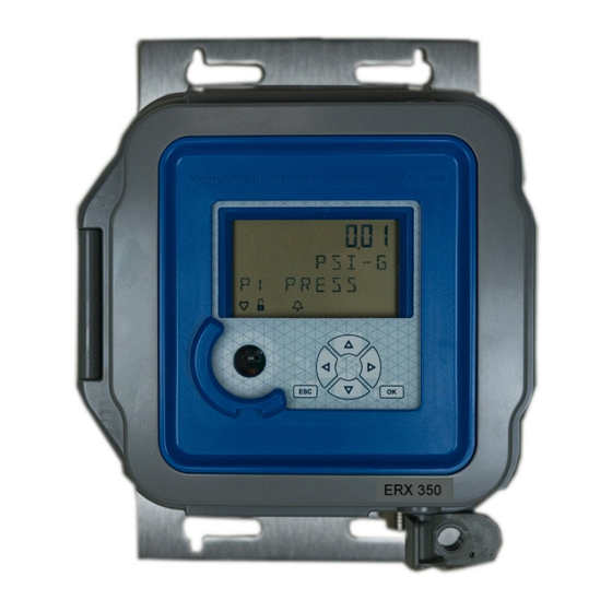
1.4 Main Interfaces of ERX350 1.4.2 LCD ERX350 provides a ten character, configurable, alphanumeric display with icons to show the status information and alarm conditions. The display can be configured to on or off at different times of day. -
Page 19: Keypad
1 About ERX350 1.4 Main Interfaces of ERX350 Icon Description Smile: Indicates the HMI is unlocked. The navigation keys are functional. Star: The Star icon turns on during pressure and temperature measurement. 1.4.3 Keypad The keypad is used for scrolling through the menu options. The following table lists the keys. -
Page 20: External Connections
1 About ERX350 1.4 Main Interfaces of ERX350 To conserve battery power, after each processing cycle the ERX350 keypad is locked, if there is no input received within the time out period (1 to 10 minutes). 1.4.4 External connections... -
Page 21: Erx350 Installation
2 ERX350 Installation This chapter deals with the installation of ERX350. This chapter also provides procedures for installing and replacing the battery and output wire connections to obtain pulse output from ERX350. ERX350 Contents Verification Overview of Installation Model Number Interpretation... -
Page 22: Erx350 Contents Verification
1. Remove the contents from the box and from the mounting kit bag. 2. Check the shipment against the invoice to ensure that the components ordered are installed in ERX350. 3. Report any shortage or shipping damages to your nearest Honeywell Account Manager. Honeywell 2023... -
Page 23: Overview Of Installation
2.2 Overview of Installation 2.2 Overview of Installation The ERX350 installation consists of mounting and wiring ERX350 according to the instructions given in this section. Before proceeding, read the installation information provided in this section and refer to the section “Model Number... -
Page 24: Model Number Interpretation
2 ERX350 Installation 2.3 Model Number Interpretation 2.3 Model Number Interpretation ERX350 is available in different models. Refer to the Model Selection Guide (MSG), available from your Honeywell Mercury sales representative, for details. Honeywell 2023... -
Page 25: Prerequisites
2 ERX350 Installation 2.4 Prerequisites 2.4 Prerequisites Ensure that the following components are installed and connected inside ERX350, before installing ERX350. Battery pack Pressure transducer (if ordered) Temperature probe (if ordered) Honeywell 2023... -
Page 26: Installing Erx350
2 ERX350 Installation 2.5 Installing ERX350 2.5 Installing ERX350 The ERX350 installation consists of mounting and wiring ERX350 per the instructions given in this section. Wall Mount Pipe Mount U-Bolt Mount Portable 2.5.1 Mounting Shown below are mounting diagrams for the ERX350 for Remote Mount and Wall Mount options: 2.5.1.1 Front / Rear Views:... -
Page 27: Side View (Right)
2 ERX350 Installation 2.5 Installing ERX350 2.5.1.2 Side View (Right) Honeywell 2023... -
Page 28: Top View (Showing Door Swing)
2.5.1.3 Top View (Showing Door Swing) 2.5.2 Pressure Line Connections Shown below are the locations for the P1 and P2 Pressure Transducer connections for ‘Wall” and “Pipe Stand” mounting installations – where connections are on bottom side of ERX350. Honeywell 2023... - Page 29 Use a pressure connector kit to connect the required pressure line(s) to the ¼ inch NPT fittings on the back side of the ERX350 enclosure. Hold pipe wrench on flats when installing a pressure line on the pressure transducer connector to ensure proper sealing and to avoid stress loading on the composite case.
-
Page 30: Electrical Connections
2 ERX350 Installation 2.6 Electrical Connections 2.6 Electrical Connections The figure below show the electrical connections of the ERX350 IO Board: Honeywell 2023... - Page 31 2 ERX350 Installation 2.6 Electrical Connections Figure 2.1 - ERX350 IO Board Overview Honeywell 2023...
-
Page 32: Power Supply Options
User Shelf/ Shutdown Mode 2.7.1 Battery Powered Connections for the Battery pack are made at the P5 connector on the ERX350 IO Board. There are three Battery choices for operating the ERX350 from battery power: 40-6050 (4-cell Alkaline) – 5 year operating life under specified conditions 40-6048 (2-cell Lithium) Dual set of 40-6048 (2-cell Lithium) –... -
Page 33: Lithium Battery Pack
Alarm is tripped (set), an Alarm Log record entry is generated along with updates to time stamp Items 462 and 463. 2.7.1.2 Lithium Battery Pack There are two choices for operating the ERX350 from a Lithium Battery pack: 40-6048 (2-cell Lithium pack) Dual set of 40-6048 (2-cell Lithium packs) – extended life or heavy comms applications... -
Page 34: External Power Supply
Honeywell power 9 VDC pack p/n: 40-2291 can be used as an external voltage source. Connections for the external supply are made at the TB1 connector on the ERX350 IO Board. Terminal-1 nearest the top of the IO Board is GND and Terminal-3 is the positive (+) input. When operating from an externally supplied DC power source, a backup battery pack may also be installed with the intent of powering the instrument in situations where the external (remote) power is interrupted. -
Page 35: Power System Measurement
2 = Dual 2 D-Cell Lithium Sealed Packs (connected in parallel), for ERX350 only 2.7.3 Power System Measurement The ERX350 power system voltage (Battery / External supply) is measured on a 10-minute interval. Three consecutively low readings are required to trip the Low Voltage Alarm (Item 99) – to help guard against falsely setting alarm due to a momentary supply glitch. -
Page 36: Digital Input / Output Wiring
Digital Outputs Pulse Outputs via the Case Connector Option The following image illustrates the I/O board of ERX350. 2.8.1 Digital Inputs Digital Inputs are limited to three (3) Alarm triggering inputs DI1 – DI3. These inputs can be configured to trip an Alarm condition based on a closed or open switch input scenario. -
Page 37: Digital Input
2 ERX350 Installation 2.8 Digital Input / Output Wiring Digital Input configuration and operation are described below: 2.8.1.1 Digital Input 1 Item 762 is Input Trigger Selection 0 = Disabled 1 = Closed Switch Alarm triggering 2 = Open Switch Alarm triggering... -
Page 38: Operations
C (normally open type) can be configured as corrected volume or uncorrected volume. Channel C can alternatively be configured as a (normally open) alarm output. Channel D (normally-closed type) is only for alarm output use. All the pulse outputs of the ERX350, including the alarm pulse output, use opto- Honeywell... - Page 39 Use of channel C Alarm signal does not disable channel D output – it remains active An alarm pulse (on channel C or D) is generated when ERX350 enters an alarm condition. Use channel C (NO or Normally Open) or channel D (NC or Normally Closed) depending on the AMR device accepting the...
- Page 40 AMR device. Volume Pulse Outputs ERX350 provides three Form-A pulse outputs (channels A, B, and C) for volume output pulses. Volume pulses can correspond to either uncorrected volume (as counted in item 2) or corrected volume (as counted in item 0). The type of volume pulse (and whether the channel is enabled) is configured through items 93-95.
-
Page 41: Modem Power Control
Use item 95 to select this feature. In this case channel C is wired either directly to a Cloud Link modem (R110 or later) in a regular ERX350 enclosure, or to the power distribution board in a MiWi350 (where power to other modems can be controlled as well). Use the Call-In and Call-Out Window features to configure modem power control. -
Page 42: 2-Wire)
2 ERX350 Installation 2.8 Digital Input / Output Wiring GND is at TB4 pin JP1 and JP2 are both across pins B-C 2.8.4.2 RS-485 (2-wire) ‘A-’ is made at TB4 pin 1 (TXD) ‘B+’ is made at TB4 pin 2 (RXD) JP1 and JP2 are both across pins A-B 2.8.5 Pulse Output Specification... -
Page 43: Pulse Outputs Via The Case Connector Option
2 ERX350 Installation 2.8 Digital Input / Output Wiring 2.8.6 Pulse Outputs via the Case Connector Option A 6 pin Amphenol case connector can be ordered to provide for the connection of two of the three pulse outputs plus the alarm from outside the instrument. The connector as shown below is viewed from out- side the instrument. -
Page 44: Installation Drawings
2 ERX350 Installation 2.9 Installation Drawings 2.9 Installation Drawings Connections to the ERX350 serial communication interface at TB4 on the I/O Board are shown in the image below. Honeywell 2023... - Page 45 2 ERX350 Installation 2.9 Installation Drawings Honeywell 2023...
- Page 46 2 ERX350 Installation 2.9 Installation Drawings Honeywell 2023...
- Page 47 2 ERX350 Installation 2.9 Installation Drawings Honeywell 2023...
- Page 48 2 ERX350 Installation 2.9 Installation Drawings Honeywell 2023...
-
Page 49: Securing The Device
3 Securing the Device This chapter describes the different safety and security features of a ERX350 device. Case Defining Access Privileges Validating Setup Configuration... -
Page 50: Case
3 Securing the Device 3.1 Case 3.1 Case The case can be locked or tamper sealed with a padlock or seal on the door hasp. Honeywell 2023... -
Page 51: Defining Access Privileges
3.2 Defining Access Privileges 3.2 Defining Access Privileges Access to the ERX350 can be controlled by defining users and assigning them passcodes and privileges. Use MasterLinkR515 & MasterLinkSQL (4.41 and above) to set up a User Table and to download it to the device. -
Page 52: Creating A User Table File
3 access. A single user can either have level 2 HMI access or level 3 HMI access or neither, but may not access both level 2 and 3. 3.2.2 Creating a User Table File To create a user table file: Honeywell 2023... - Page 53 3 Securing the Device 3.2 Defining Access Privileges 1. Establish a serial communication between ERX350 and MasterLinkR515 & MasterLinkSQL. Refer to the MasterLinkSQL User’s Guide for information about establishing a serial connection between ERX350 and MasterLinkR515 & MasterLinkSQL. 2. In the MasterLinkSQL window, click Instrument > Edit User Table.
-
Page 54: Sending A User Table File
3.2.3 Sending a User Table File To send a user table file: 1. Establish a serial communication between ERX350 and MasterLinkR515 & MasterLinkSQL. Refer to the MasterLinkSQL User’s Guide for information about establishing a serial connection between ERX350 and MasterLinkR515 & MasterLinkSQL. - Page 55 3 Securing the Device 3.2 Defining Access Privileges 2. In the MasterLinkSQL window, click Transfer > Send User Table. The ERX350 ships in unsecure mode with default passwords. Change the default passcodes at least to secure the device. Note: For convenient device access by users choosing not to secure their devices, MasterLinkR515 &...
-
Page 56: Validating Setup Configuration
3 Securing the Device 3.3 Validating Setup Configuration 3.3 Validating Setup Configuration After installing ERX350 on the meter and updating its configuration settings, ensure to perform the following final checkout tasks: Verify the pulse input. Refer to the section “Testing the Pulse... -
Page 57: Key Features
4 Key Features This chapter describes the key features of an ERX350 device. -
Page 58: P-T Measurement
With each 30 second measurement, the gas pressure correction factor is computed and high and low Pressure alarms are checked (regardless of flow rate conditions). The ERX350 uses a high resolution analog to digital conversion process to produce a very accurate final reading. - Page 59 P2 Min pressure time (item430) P2 Min pressure date (item431) Note: The P3 pressure sensor is not applicable for the ERX350 device. Following are several of the P4 pressure statistical items: P4 RBX Deadband Pressure (item 1640) P4 Interval Average Pressure (item 1641)
-
Page 60: Gas Temperature
P4 Previous Day Low Pressure (item 1665) P4 Previous Day Low Pressure Time (item 1666) P4 Previous Day Low Pressure Date (item 1667) Note: P4 value shows an error code (9999) if any one of the sensor is disconnected. 4.1.2 Gas Temperature Honeywell 2023... -
Page 61: Temperature Statistics
With each 30 second measurement, the gas temperature correction factor is computed and high and low Temperature alarms are checked (regardless of flow rate conditions). The ERX350 uses a high resolution analog to digital conversion process to produce a very accurate final reading. -
Page 62: Alarms
4.2 Alarms 4.2 Alarms ERX350 monitors a list of parameters and compares their measured values to configurable limits to determine if a fault condition has occurred. When any of these measured parameters has exceeded their respective limit, ERX350 will create an Alarm. - Page 63 Record CRC 1410 internal error encountered during record search/read Alarm error Audit Log n/a - n/a - internal if > 0, some number of corrupt records were Record CRC 1411 internal error encountered during record search/read Alarm error Honeywell 2023...
-
Page 64: Pressure Low
Alarm Value Alarm Value alarm value Report By Exception (RBX) RBX (Report By Exception) is an alarm mode that is enabled via item 165. RBX controls the behavior of the following alarms. Pressure 1 High Pressure 1 Low Honeywell 2023... -
Page 65: Pressure Low Limit
(hysteresis). The deadband values are specified in items 166 (Pressure 1), 167 (Temperature), and 459 (Pressure 2). When disabled, the alarms remain in their current state until the user manually clears it. Honeywell 2023... -
Page 66: Logging
Log Record Integrity Verification 4.3.1 Audit Trail Logging Configuration Using MasterLink software, an ERX350 device can be configured to contain as many as 5 independent logs, each with its own collection of item values and collection (sample) frequency. Each log can be con- figured to collect values for up to 20 items. - Page 67 5. You can save a configuration for future reference to a configuration file (*. cnfg) with the Save setup to file button. It can later be retrieved with the Read setup form file button. Only *. cnfg files can be read; item files (*.ie3) are not compatible. Honeywell 2023...
- Page 68 4 Key Features 4.3 Logging 6. You can right click on the time interval displayed in the Log Configuration tree, to configure the period at which log records are recorded. Honeywell 2023...
- Page 69 Days worth of data as well as the Number of records that can be written before overwriting will occur. Note: Note: A log’s interval setting will impact Days, but not Numbers. Honeywell 2023...
-
Page 70: Reading Audit Trail From The Erx350
ERX350 for all data it has collected since then. Using this option each time will ensure that the host database contains a complete set of audit trail records for each log in each instrument. -
Page 71: Displaying/Viewing Audit Trail Reports
Trail data to view. 2. Click the Select Sites button to browse to the desired ERX350 unit by SITE ID/ Site name. 3. Click on the Date Range tab to bring up a control window to select date range display options for the log report. -
Page 72: Supported Event Codes
SYSTEM EVENTS DAILY LIMIT 23 BATTERY LIFE RESET FIRMWARE UPGRADE 4.3.3.2 Clearing Event Log To clear the event log: Write a value of 19230429 to item 264 using Setup > Advanced>Raw Instrument Access >Raw Item Access in MasterLinkR515 & MasterLinkSQL. Honeywell 2023... -
Page 73: Log Record Integrity Verification
Compare the CRC value on the device display with the one in the Audit Trail CSD file or the Event Log report. The UP and DOWN arrow keys can be used to show the previous or next record. Honeywell 2023... -
Page 74: Battery Life/ Usage Tracking
Alkaline Battery– Item 48 tracks the Battery voltage and Item 49 is the configurable Low Limit for tripping a low Battery Alarm condition. Item 50 is the configurable Low Limit for putting the ERX350 in to a low Battery ‘shutdown’ condition – ending most of its operations to greatly con- serve the battery power. -
Page 75: Display On/Off
4 Key Features 4.5 Display ON/OFF 4.5 Display ON/OFF The ERX350 display can be configured to turn on and off at specific times during the day. You can configure this in the MasterLink software using the following item codes: Item Code... -
Page 76: User Access
5 User Access This chapter provides an overview on using a ERX350 device. It includes information on how to work with HMI displays and how the connections must be done between ERX350 and MasterLink. Getting Started with the Keypad Working with HMI Connecting to ERX350 via MasterLinkR515 & ... -
Page 77: Getting Started With The Keypad
HMI keypad modes. 5.1.2 Human Machine Interface (HMI) It provides access to the information about ERX350. You can configure the information using the integral display panel and keypad. HMI keypad mode can be classified into the following four sub-levels. -
Page 78: Level 0 Mode
5 User Access 5.1 Getting Started with the Keypad of ERX350. This mode provides six submenus. You can view and configure the items in this mode by scrolling through the six submenus. A passkey is required to access this mode. - Page 79 Scroll List mode has a 60- second inactivity time-out. If you do not press any key for 60 consecutive seconds, ERX350 exits the level 0 mode and returns to the normal Corrector mode.
-
Page 80: Level 1 Mode
1. Press and hold the ESC and UP arrow at the same time for about three seconds or until the following Display Test appears. This unlocks the ERX350 keypad and ERX350 enters the HMI keypad mode. 2. Press the DOWN arrow. - Page 81 Cloud Link Diagnostics The level 1 mode is read-only mode where you can view alarms, firmware, and configuration information. Perform the following steps to enter the level 1 mode. The following flowchart illustrates the items in level 1 mode. Honeywell 2023...
- Page 82 5 User Access 5.1 Getting Started with the Keypad Honeywell 2023...
- Page 83 The individual alarm items are not displayed in the L1.2 menu, unless that particular alarm is active. Alarm 1465 TMPR AL DT L1.2 ALARMS Information 1464 TMPR AL TM TAMPER ALM P1 AL DT P1 AL TM P1 DCR AL Honeywell 2023...
- Page 84 Site Identification #2 L1.3 INSTRUMENT Information DATE Instrument Date TIME Instrument Time BATT % REM 1002 Battery % Life Remaining BATT VOLTS Battery Voltage Reading EXTERNL 1046 External Supply Voltage BATT TYPE 1061 Battery Type DEF DISPLAY LCD Default Display Honeywell 2023...
- Page 85 GAS TEMP Gas Temperature Temperature T-PROB TYP 1185 Temp Probe Type L1.5 TEMPERATURE Information T-PROB RNG 1186 Temp Probe Range TEMP UNITS Temperature Units T-PROB S/N 1187 Temp Probe Serial No. CASE TEMP Case Temperature Honeywell 2023...
- Page 86 User Access Type Communication Serial Comm Format L1.6 COM PROTCL FORMAT Protocol COMM TYPE 1220 Serial Comm Type HANDSHAKE 1221 Serial Handshake Type COMWAKEUP 1219 Serial Wakeup Method TIMEOUT Timeout Delay 1 DEL 1 TIMEOUT Timeout Delay 2 DEL 2 Honeywell 2023...
- Page 87 CLOUD LINK LAST IP AD COMM STAT CL RADI FW BATT VOLTS MODEM TYPE BLE SECURT CL MAIN FW FW CHK SUM PULSE CNT PAIRED DEV Accessing level 1 read only mode To access level 1 read only mode: Honeywell 2023...
- Page 88 1. Press and hold the ESC and UP arrow at the same time for about three seconds or until the following Display Test appears. This unlocks the ERX350 keypad and ERX350 enters the HMI keypad mode. 2. Press OK to enter level 1 mode.
-
Page 89: Level 2 Mode
Level 2 mode is the limited-access configuration mode and provides read-only information on the following: Passcode Alarms Clear Alarms Configuration Verify Pressure Verify Temperature Diagnostics View logs Shutdown Battery Change Reset Communication The following flowchart illustrates the main menus and submenus in the level 2 mode. Honeywell 2023... - Page 90 ALARMS is activated on the next measurement. L2.4 CONFIG Allows you to configure the Level 2 sub-menu 1 items. L2.4.1 ALARMS L2.4.1.1 LIMITS L2.4.1.1.1 P HI LIMIT Honeywell 2023...
- Page 91 L2.4.2.1.2 FW VERSION L2.4.2.1.3 SITE ID #1 L2.4.2.1.4 SITE ID #2 L2.4.2.1.5 CONV TYPE L2.4.2.1.6 DATE L2.4.2.1.7 TIME L2.4.2.1.8 DEF DISPLY L2.4.2.2 BATTERY L2.4.2.2.1 BATT TYPE L2.4.2.2.2 BAT LO LIM L2.4.2.2.3 BAT MO LIM L2.4.2.2.4 EXTRN L LIM Honeywell 2023...
- Page 92 L2.4.3.1.8 P-FAC CALC L2.4.3.1.9 FIXED P L2.4.3.2 BASE PRESS L2.4.3.3 ATMS PRESS L2.4.4 TEMPERATUR L2.4.4.1 GAS TEMP L2.4.4.1.1 GAS TEMP L2.4.4.1.2 TEMP UNITS L2.4.4.1.3 T-PROB TYP L2.4.4.1.4 T-PROB RNG L2.4.4.1.5 T-PROB S/N L2.4.4.2 BASE TEMP L2.4.4.3 CASE TEMP Honeywell 2023...
- Page 93 DIG TRIG 3 L2.4.6.1.2 CLOUD LINK L2.4.6.1.3 L2.4.6.2.1 VERIFY P/T L2.4.6.2.2 VALIDATE P1 L2.4.6.2.3 VALIDATE T L2.4.6.3 VALIDATE P2 L2.4.6.3.1 VALIDATE P3 L2.4.6.3.2 VALIDATE P4 Allows you to validate the accuracy of the L2.5 VERIFY P/T pressure/temperature measured by ERX350. Honeywell 2023...
- Page 94 VALIDATE P display, Use the keypad to enter or change the value of pressure/ temperature that ERX350 must measure. After you enter the value, press. The ERX350 calculates the % ERROR. %ERROR is the difference between the pres- L2.5.2 VALIDATE T sure/temperature value measured by ERX350 and the value (the entered value) that ERX350 must measure.
- Page 95 1. Press and hold the ESC and UP arrow at the same time for about three seconds or until the Display Test (all segments on) appears. This unlocks the ERX350 keypad and ERX350 enters the HMI keypad mode. 2. Press OK to enter level 2 mode.
- Page 96 12. Use the UP arrow and DOWN arrow to scroll through the submenu items in level 2 mode. 13. Press OK to select the necessary submenu. 14. Press ESC to return to the main menu item. 15. From the main menu item, press ESC to exit level 2 mode. Honeywell 2023...
-
Page 97: Level 3 Mode
Level 3 mode is the limited-access configuration mode and provides read-only information on the following: Passcode Alarms Clear Alarms Configuration Advance Configuration Verify Pressure Verify Temperature Calibrate Pressure Calibrate Temperature Diagnostics View logs Shutdown Modem calls The following flowchart illustrates the items in level 3 mode. Honeywell 2023... - Page 98 Allows you to clear the active alarms on the display. If the L3.3 condition that caused the alarm is still present, a new alarm ALARMS is activated on the next measurement. L3.4 CONFIG Allows you to configure the Level 2 sub-menu 1 items. L3.4.1 ALARMS Honeywell 2023...
- Page 99 L3.4.2 INSTRUMENT L3.4.2.1 SITE INFO L3.4.2.1.1 UNIT S/N L3.4.2.1.2 FW VERSION L3.4.2.1.3 SITE ID #1 L3.4.2.1.4 SITE ID #2 L3.4.2.1.5 CONV TYPE L3.4.2.1.6 DATE L3.4.2.1.7 TIME L3.4.2.1.8 DEF DISPLY L3.4.2.2 BATTERY L3.4.2.2.1 BATT TYPE L3.4.2.2.2 BAT LO LIM Honeywell 2023...
- Page 100 L3.4.3.1.6 P-XDCR S/N L3.4.3.1.7 PRESS FACT L3.4.3.1.8 P-FAC CALC L3.4.3.1.9 FIXED P L3.4.3.2 BASE PRESS L3.4.3.3 ATMS PRESS L3.4.4 TEMPERATUR L3.4.4.1 GAS TEMP L3.4.4.1.1 GAS TEMP L3.4.4.1.2 TEMP UNITS L3.4.4.1.3 T-PROB TYP L3.4.4.1.4 T-PROB RNG L3.4.4.1.5 T-PROB S/N Honeywell 2023...
- Page 101 TMOUT DEL3 DIGI SE IN L3.4.6 DIG TRIG 1 L3.4.6.1 DIG TRIG 2 L3.4.6.1.1 DIG TRIG 3 L3.4.6.1.2 CLOUD LINK L3.4.7 ADVANCED L3.5 CONFIG Allows you to validate the accuracy of the L3.6 VERIFY P/T pressure/temperature measured by ERX350. Honeywell 2023...
- Page 102 VALIDATE P display, Use the keypad to enter or change the value of pressure/ temperature that ERX350 must measure. After you enter the value, press. The ERX350 calculates the % ERROR. %ERROR is the difference between the pres- L3.6.2 VALIDATE T sure/temperature value measured by ERX350 and the value (the entered value) that ERX350 must measure.
- Page 103 L3.18 UNPAIR BLE YES /NO To access level 3 mode: 1. Press and hold the ESC and UP arrow at the same time for about three seconds or until the fol- lowing Display Test (all segments on) appears. Honeywell 2023...
- Page 104 5 User Access 5.1 Getting Started with the Keypad This unlocks the ERX350 keypad and ERX350 enters the HMI keypad mode. 2. Press OK to enter level 3 mode. The level 3 mode PASSCODE screen appears. Honeywell 2023...
- Page 105 If the log in was successful, the display indicates that you are in level 3 mode. If the user ID or passcode were invalid, you will be returned to the main level 1 menu. 10. Use the UP arrow and DOWN arrow to scroll through the main menu items (L3.2 through L3.10) in Honeywell 2023...
- Page 106 12. Use the UP arrow and DOWN arrow to scroll through the submenu items in level 3 mode. 13. Press OK to select the required submenu. 14. Press ESC to return to the main menu item. 15. From the main menu item, press ESC to exit level 3 mode. Honeywell 2023...
-
Page 107: Working With Hmi
5. Press OK. The live pressure measurement made by the instrument appears on the display. For example: 51.00 LIVE PRESS The pressure value that appears in this step is the value that ERX350 reads. 6. Press OK. For example, the following appears on the display. 50.00 Honeywell... -
Page 108: Verifying Temperature
5 User Access 5.2 Working with HMI INPUT REFP 7. Enter the reference pressure (the actual/exact pressure being piped to ERX350) using the keypad and press The percentage difference between the pressure that ERX350 reads and the reference pressure appears on the display. -
Page 109: Entering The Site Id
5.2 Working with HMI For example: 75.20 LIVE TEMP Here, 75.20 is the value that ERX350 reads and F stands for the unit of temperature that is Fahren- heit. 7. Press OK. The following appears on the display. 75.20 INPUT REFT Here, REFT stands for reference temperature. -
Page 110: Setting The Date And Time
“Accessing Level 2 Mode” for accessing level 2 mode or section “Access Level 3 Mode” for accessing level 3 mode. 2. By default, in level 2 mode or level 3 mode the following appears on the display. MAIN MENU ALARMS Honeywell 2023... -
Page 111: Setting The Time
3. Using the UP arrow and DOWN arrow scroll through the options in level 2 mode or level 3 mode until CONFIG appears. 4. Press OK. The following appears on the display. CONFIG ALARMS 5. Using the UP arrow and DOWN arrow scroll through the options in level 2 mode or level 3 mode Honeywell 2023... - Page 112 7. Press OK, the following appears on the display. UNIT S/N 8. Using the UP arrow and DOWN arrow scroll through the options until TIME appears. 9. Press OK. 10. Using the keypad set the TIME and press OK. Honeywell 2023...
-
Page 113: Auto Set Date And Time
5.2.4.3 Auto set date and time At regular intervals, the date and time information for the ERX350 device is logged in audit logs. Whenever there is a power reboot, the device retains the date and time from the last saved audit log. -
Page 114: Selecting The Unit Of Measurement For Temperature
10. Press OK to select the required unit. For example, if you press OK at Code 0, PSI is selected as the unit of PRESSURE. 5.2.5.2 Selecting the Unit of Measurement for Temperature To select the unit of measurement for temperature: Honeywell 2023... - Page 115 9. Press OK and then using the UP arrow and DOWN arrow increase or decrease the value of Code. The corresponding unit associated with the code appears. For example, Code 0 represents F. Following are the codes and the corresponding units of measurement for PRESSURE. Code Units Code 0 F Code 1 C Honeywell 2023...
-
Page 116: Single Point Temperature And Pressure Calibration
4. Press OK. The following appears on the display. CALIB P/T CALIB PRES 5. Press the DOWN arrow, the following appears on the display. CALIB P/T CALIB TEMP Press OK, the temperature read by ERX350 appears on the display. For example: 75.20 Honeywell 2023... -
Page 117: Calibrating Pressure
5 User Access 5.2 Working with HMI LIVE TEMP Here, 75.20 is the value that ERX350 reads and F stands for the unit of temperature that is Fahrenheit. 6. Press OK. The following appears on the display. 75.20 INPUT REFT Here, REFT stands for reference temperature. - Page 118 6. Press OK. The following appears on the display. 50.00 INPUT REFP 7. Enter the reference pressure (the actual/exact pressure being piped to ERX350) using the keypad and press OK. The percentage difference between the pressure that ERX350 reads and the reference pressure appears on the display.
-
Page 119: Connecting To Erx350 Via Masterlinkr515 & Masterlinksql
1. Insert the dongle into the magnetic pipe boot. Ensure that the cable passes through the hook provided in the magnetic pipe boot to prevent the dongle from displacing. 2. Place the boot on ERX350. Ensure that the leg of the boot is above the eyebrow. Honeywell... -
Page 120: Updating Erx350 Firmware
Updating ERX350 Firmware ERX350 is provided with a built-in firmware loader that allows new versions of firmware to be installed easily. Firmware can be upgraded using the Firmware Upgrader option available in the MasterLinkR515 & MasterLinkSQL software. When you select this option, the MasterLinkR515 & MasterLinkSQL software works with the built-in loader of ERX350 and provides a very robust system for upgrading the ERX350 firmware. - Page 121 5 User Access 5.3 Connecting to ERX350 via MasterLinkR515 & MasterLinkSQL The firmware upgrade is performed through the IrDA serial interface that is used by the MasterLinkR515 & MasterLinkSQL software. The IrDA serial interface provides an electrically isolated interface and requires no additional hardware or software beyond what is already needed to utilize the MasterLinkR515 & ...
- Page 122 5 User Access 5.3 Connecting to ERX350 via MasterLinkR515 & MasterLinkSQL 2. To select the firmware file, click Browse and navigate to the path where the ERX350 firmware file is saved. 3. From the Serial Port list, select USB IrDA.
- Page 123 5.3 Connecting to ERX350 via MasterLinkR515 & MasterLinkSQL 6. Click OK only if you have saved ALL (Calibration and non-Calibration) items in ERX350. The program begins to load the new firmware and then validates its integrity. Once the firmware is validated, the firmware is sent to the MasterLinkR515 & ...
-
Page 124: Force Schedule Call-In Time After Fw Update
5 User Access 5.3 Connecting to ERX350 via MasterLinkR515 & MasterLinkSQL the following image. 8. After the upgrade is complete, Upgrade was successful (in green) appears at the lower left corner of the main Firmware Upgrader dialog box. 9. Click Exit to close the Firmware Upgrader dialog box. -
Page 125: Working With Masterlinkr515 & Masterlinksql
5.4.1 Items by Function 1. To select items (for viewing and modifying) by their functional categories: Establish a serial communication between ERX350 and MasterLinkR515 & MasterLinkSQL. Refer to the MasterLinkSQL User’s Guide for information about establishing a serial connection between ERX350 and MasterLinkR515 & ... -
Page 126: Setting Time And Date
A dialog appears allowing the user to accept the date and time update. 3. Click the Yes button to proceed with the Date/Time update. MasterLinkR515 & MasterLinkSQL will always re-read the PC’s clock date and time just before sending the data packet over to ERX350. 5.4.3 Item Files... -
Page 127: Displaying/Viewing Item Files
5.4.3.2 Displaying/Viewing Item Files To display or view item files: 1. Establish a serial communication between ERX350 and MasterLinkR515 & MasterLinkSQL. Refer to the MasterLinkSQL User’s Guide for information about establishing a serial connection between ERX350 and MasterLinkR515 & MasterLinkSQL. - Page 128 5 User Access 5.4 Working with MasterLinkR515 & MasterLinkSQL 2. Apply a zero reference pressure (0.00 PSI) to the P1 pressure transducer of ERX350. Wait for the pressure reading displayed on the Pressure 1 dialog box to stabilize. 3. After the reading stabilizes, click Average Pressure Now.
-
Page 129: Calibrating Temperature
11. Change the value to accurately match the high reference pressure applied to the pressure transducer. 12. Click OK. The Restore Line Pressure dialog box appears. 13. Restore the normal pressure line to ERX350 and click Done to exit the calibration. 5.4.5 Calibrating Temperature Attention: Attention: Check the sensors before calibrating temperature. - Page 130 7. Click Span Calib. The Temperature Span Calibration page appears. 8. Insert the temperature probe of ERX350 and the calibrated thermometer into a high temperature bath, which provides the temperature span reference. The temperature reading displayed on the Temperature Calibration dialog box must exceed the zero reference temperature by at least 15% to proceed with span calibration.
-
Page 131: Configuring The Scroll List
5.4.6 Configuring the Scroll List When you access the Meter reader mode of ERX350, 12 default items are available on the display. Press the down arrow to sequentially scroll through items. Refer to the section “Level 0 Mode” for the 12 default items. - Page 132 The Display/Change Items By Function dialog box appears. 2. Double click the Site Information option and enter the site ID. 3. The site ID must be identical to the one configured in PowerSpring during the ERX350 product addition. It is a six digit, hexadecimal number.
- Page 133 6. Specify the log interval size (this should match the interval size specified in the Input field definition in PowerSpring). Configure the Audit Trail items of ERX350 from the left pane. The sequence and number of Audit Trail items must match the inputs provided for RUID Inputs on Definition page in PowerSpring.
- Page 134 491, 492, 494,495, 496, up to last). Critical items are, 339 & 493, where the Host machine's IP Address for MERCURYSERVER and TCP Port (50467) should be correctly specified. The remaining fields can be defined by the user. Honeywell 2023...
- Page 135 Note: The Corrected Volume # of digits is defined for item-90, 97 and the Uncorrected Volume # of digits is defined for item-92, 97 These values must match the No. of Dials field in the Unit Configuration tab in PowerSpring. Honeywell 2023...
-
Page 136: Working With Powerspring
5 User Access 5.5 Working with PowerSpring 5.5 Working with PowerSpring Once the ERX350 is added to PowerSpring, the configuration can be done based on your requirement. Adding ERX350 to PowerSpring 5.5.1 Adding ERX350 to PowerSpring To add ERX350 to PowerSpring 1. - Page 137 5 User Access 5.5 Working with PowerSpring 4. Specify the device configuration details. Note: Note: Remote Unit ID (RUID) and FirmWare version must be the same as specified in ERX350. The Instrument Type must be selected as MERCURY ERX350. Honeywell 2023...
- Page 138 6 Remote Communications This chapter describes the different communication mechanisms featured in a ERX350 device. Use of RS232/ 485 Call in and Call out Modbus Host Communication...
-
Page 139: Remote Communications 6.1 Rs232
6.1 RS232/ 485 6.1.1 Application ERX350 is capable of communicating with a number of types of external devices, such as cellular or land- line modems, and RTUs. ERX350 supports the following protocols: MI Protocol, Modbus RTU, Modbus ASCII. The description of those protocols is beyond the scope of this manual, although a basic discussion of Modbus operation is presented later in this chapter. -
Page 140: Jumpers
B and C as shown in the picture above. They must be placed on A and B for RS-485. 6.1.4 Configuration Parameters ERX350 items in the ‘Communications’ group in MasterLink may need to be modified to accommodate a particular external device. -
Page 141: Connecting Erx350 With Modems
6 Remote Communications 6.2 Connecting ERX350 with Modems 6.2 Connecting ERX350 with Modems Follow the steps below to connect a ERX350 device with PowerSpring using a Messenger Modem: Configure ERX350 using MasterLink Configure ERX350 in PowerSpring 6.2.1 Configure ERX350 using MasterLink Launch MasterLink, and go to DISPLAY tab in tool bar and click on Item by Function option. - Page 142 LOG INTERVAL size (this should match with the interval size given in Input definition of the PowerSpring.) Configure the AUDIT TRAIL items of ERX350, from left pane with the sequence & number of Audit Trail items equal to PowerSpring RUID Inputs Definition page.
- Page 143 6 Remote Communications 6.2 Connecting ERX350 with Modems 3. Call-In Configuration: Inside the Display/Change Items By Function sub-window, double click on Call-In Config option. Enter the information as shown in the region marked in red.i.e. items 1230, 333, 491, 492, 494,495, 496, up to last – depending on how the user wants the Call- in to happen.
- Page 144 6 Remote Communications 6.2 Connecting ERX350 with Modems 4. Corrected Volume # of digits: item-90, 97 Uncorrected Volume # of digits: item-92, 97 These values should be match with the “No. of Dials field”, in UNIT configuration in PowerSpring input configuration.
-
Page 145: Configure Erx350 In Powerspring
6 Remote Communications 6.2 Connecting ERX350 with Modems 6.2.2 Configure ERX350 in PowerSpring 1. Go to the PowerSpring dashboard and inside the Configuration list, click on the Remote Units. Click on ADD NEW button. Honeywell 2023... - Page 146 6 Remote Communications 6.2 Connecting ERX350 with Modems 2. In the Product type dropdown, select the ERX350 product type. Honeywell 2023...
- Page 147 Note: Note: Remote Unit ID (entered in New Remote Unit ID), FirmWare version, should be same as is specified in ERX350 corrector and the Instrument Type must be selected as MERCURY ERX350. 3. Click on ADD Button in left bottom.
- Page 148 6 Remote Communications 6.2 Connecting ERX350 with Modems 4. In the General tab enter all the applicable information and enable the device ACTIVE check box. Honeywell 2023...
- Page 149 6 Remote Communications 6.2 Connecting ERX350 with Modems 5. In the Call tab, in the Other Information sub-window, specify the type of communication i.e. IP Enabled or Not. Honeywell 2023...
- Page 150 6 Remote Communications 6.2 Connecting ERX350 with Modems 6. The sequence and number of inputs inside the INPUTS tab must be identical to ERX350 Audit Trail Log1. Honeywell 2023...
- Page 151 6 Remote Communications 6.2 Connecting ERX350 with Modems Click on EDIT tab on the Input to be edited. Honeywell 2023...
- Page 152 6 Remote Communications 6.2 Connecting ERX350 with Modems In EDIT Input window > Input Definition, enter the following critical parameters: a. Input description b. Input Interval c. Enable the Billable option d. Save Data (enable checkboxes to store the Interval, Time of Call, Daily Reading) e.
- Page 153 6 Remote Communications 6.2 Connecting ERX350 with Modems INPUTS>Central Data Alarms tab: Use this tab to define automatic central limit checking. PowerSpring allows you to set up a simple, yet extremely effective, Central Interval Level Checking scheme that enables you to report on intervals outside user-configured boundaries.
- Page 154 6 Remote Communications 6.2 Connecting ERX350 with Modems above this level, call the customer. Central Interval 3 High - Set his to the highest level of severity. If consumption rises above this level, you know that the customer is using gas Inside the Edit Input (Corrected Volume) window, go to the UNITS tab.
- Page 155 6 Remote Communications 6.2 Connecting ERX350 with Modems data, using the Custom Report and Data Viewer applications, and view the data in a new format. Most important information, the latest ADDED field or REPORT units will be used to save the data, since when they are created. Previous existing units shall still show the history in the respective units.
- Page 156 6 Remote Communications 6.2 Connecting ERX350 with Modems Honeywell 2023...
- Page 157 6 Remote Communications 6.2 Connecting ERX350 with Modems Once user clicks on ADD button, the entered unit and factors should be added and publish in the dropdown list of available UNITS. Honeywell 2023...
- Page 158 6 Remote Communications 6.2 Connecting ERX350 with Modems SAVE the changes and reopen the UNITS window for selected input. The added REPORT UNIT should be listed in the REPORT units dropdown as shown below: Honeywell 2023...
- Page 159 6 Remote Communications 6.2 Connecting ERX350 with Modems Specify the date from when this report unit will be applicable for data calculation. Also define the description of this report unit for easy identification as is shown in below screenshot:...
- Page 160 6 Remote Communications 6.2 Connecting ERX350 with Modems Honeywell 2023...
- Page 161 6 Remote Communications 6.2 Connecting ERX350 with Modems Click on SAVE button. Once the new report unit is available in dropdown, now user can associate this report unit to any inputs existing in the database. To validate this UNIT is available for calculation; verify it in DATA...
- Page 162 6 Remote Communications 6.2 Connecting ERX350 with Modems Note: Note: The Operator and Factors given for the REPORT or FIELD UNITS should be used correctly in DATA VIEWER. In the below screenshot user can see the SCM report unit contains the Operator1=* and Factor1=10.
- Page 163 6 Remote Communications 6.2 Connecting ERX350 with Modems 7. Alarms tab for Remote Unit Honeywell 2023...
- Page 164 6 Remote Communications 6.2 Connecting ERX350 with Modems Navigate to ALARMS tab as and configure the ALARMS for ERX350 device, user can configure the alarms thathe wants to display in PowerSpring Alarm/System Monitor application. As shown below user has to EDIT the existing alarm.
- Page 165 Note: Alert Mode: Select the Notify Immediately check box to enable the Remote Unit to call immediately when the selected hardware alarm is detected. Another critical purpose of CLEAR ALARMS checkbox is that it will clear the hardware alarms in the device (i.e. ERX350) once the call is successful in PowerSpring.
- Page 166 6 Remote Communications 6.2 Connecting ERX350 with Modems Save - Saves the selected Hardware alarm occurrence to the database (Alarm Data File). Log - Logs the selected Hardware alarm occurrence to your alarm logging device. This logging device, usually a printer, is specified in the Alarm Maintenance application.
- Page 167 6 Remote Communications 6.2 Connecting ERX350 with Modems Honeywell 2023...
- Page 168 6.3 Call-In and Call-Out 6.3 Call-In and Call-Out Call-In Call-Out 6.3.1 Call-In ERX350 has the capability to initiate a modem to modem telephone call. This is called call in and can happen under two circumstances. Alarm Call-In Scheduled Call-In. 6.3.1.1 Call-In When connected to either a cellular or landline modem the ERX350 can be configured to autonomously dial and connect to a host computer.
- Page 169 6.3.1.2 Scheduled Call-In The ERX350 can initiate a call at a preset time. The time may have been manually specified, but on an ongoing basis the host(s) is responsible for the schedule. At the end of each call the host is must set item values that determine when the next call is to take place.
- Page 170 Not all call failures are resolved with ‘retries’. ‘Retries’ is defined as the termination of the current attempt and the scheduling of another attempt some minutes or hours hence. In some cases the ERX350 may try to resolve the failure immediately. If, for instance, an initialization string is sent to the modem but no positive response is received within several seconds, it will simply send it again.
- Page 171 ERX350 can also be kept “awake” during the call out window(s) such that even the initial characters of a communication session are accepted. Otherwise, the initial characters “wake up” the ERX350. The MI Protocol includes such wake up characters in its protocol so that this feature is not required for MI Protocol communication.
- Page 172 6 Remote Communications 6.3 Call-In and Call-Out 1. Establish a serial communication between ERX350 and MasterLinkR515 & MasterLinkSQL. Refer to the MasterLinkSQL User’s Guide for information about establishing a serial connection between ERX350 and MasterLinkR515 & MasterLinkSQL. 2. In the MasterLinkSQL window, click Find Item by Number icon.
- Page 173 6 Remote Communications 6.3 Call-In and Call-Out 4. Click Change. The Change Item dialog box appears. 5. Enter the desired stop time and click Save. 6. Repeat steps 2 to 5 if you want to change item 1234. Honeywell 2023...
- Page 174 Modbus registers can be ‘mapped’ to items in the ERX350 via the items in the following group. For example, pressure can be mapped to register 7003 by enabling Float mapping in item 935 and setting item 943 to ‘8’.
- Page 175 6 Remote Communications 6.4 Modbus Communication Honeywell 2023...
- Page 176 7 Maintenance This chapter lists out the temperature and transducer related kits. It also includes information on how to remove the HF cover. Temperature Probe Measurement Kits Transducer Replacement Kits Metrological Sealing Cover (MC) Installing Measurement Canada (MC) Sealing Cover Removing and Re-Installing Human Factor (HF) Cover...
- Page 177 40-6007-KIT 3" Pete’s Plug Armored 40-6005-1-KIT 2-1/8" Pete’s Plug Teflon 40-6005-2-KIT 3" Pete’s Plug Teflon 3' Cable 40-6005-3-KIT 3" Pete’s Plug Teflon 10 ' Cable 40-6002-KIT External Teflon 40-6003-KIT 3/16" Sheath Teflon 40-6004-KIT 6" Sheath 6' Teflon Cable Honeywell 2023...
- Page 178 1500 psig 22-2950-9-KIT 15 psig 22-2950-10-KIT 150 psig 22-2950-11-KIT 200 psig 22-2950-12-KIT 30 psia 22-2950-13-KIT 60 psia 22-2950-14-KIT 100 psia 22-2950-15-KIT 300 psia 22-2950-16-KIT 600 psia 22-2950-17-KIT 1000 psia 22-2950-18-KIT 1500 psia 22-2950-19-KIT 150 psia 22-2950-20-KIT 200 psia Honeywell 2023...
- Page 179 7 Maintenance 7.2 Transducer Replacement Kits Honeywell 2023...
- Page 180 MC cover sealing features. 3. Re-install Human Factor cover tightening the screws to 9 +/- 1 in-lbs of torque at these locations. Ensure power cable is routed in the orientation shown for battery connection. Honeywell 2023...
- Page 181 7.4 Replacing the Battery Pack 7.4 Replacing the Battery Pack If your ERX350 displays REPLACE BATTERY, it indicates that ERX350 has gone into a power conservation mode due to low battery voltage. Replacing the Battery in a Hazardous DIV-1/ZONE-0 Environment...
- Page 182 To replace the battery in a hazardous DIV-1/ZONE-0 environment, perform the following steps: 1. Enter HMI and set the ERX350 to Battery Change mode. You can use the L2.11 or L3.13 HMI menus. 2. The BATT CHNG message is displayed on the display screen. Press the Enter key.
- Page 183 Enter key. c. Press YES key to confirm (see note below). d. ERX350 resets the battery usage Items to factory default values: (Item 59 = 0, Item 1001 = 60 mo, Item 1002 = 100%). e. Press ESC until you have exited the HMI.
- Page 184 7.6 Low battery/ External Power Shutdown Mode 7.6 Low battery/ External Power Shutdown Mode ERX350 automatically enters a low battery shutdown mode when the battery voltage measurement falls below the value of Item 50 (Battery Shutdown Limit) for three (3) consecutive times.
- Page 185 Refer to the table below to see which functionality is not blocked in shutdown mode Functionality What Happens Alarm logging Runs as normal. However it is unlikely to have any alarms Event logging Runs as normal HMI Menus and Scroll List Active- No live readings are taken Honeywell 2023...
- Page 186 7.7 User Shelf/ Shutdown mode The ERX350 can be placed in to a User Shelf / Shutdown mode to take it out of service for extended periods of time. This mode is useful to conserve battery life when the instrument is not in use. In this mode ERX350 conserves battery energy by limiting most of its normal functionality while preserving data and keeping time.
- Page 187 Refer to the table below to see which functionality is not blocked in User Shelf mode. Functionality What Happens Alarm logging Runs as normal. However, it is unlikely to have any alarms Event logging Runs as normal HMI Menus and Scroll List Active- No live readings are taken Honeywell 2023...
Need help?
Do you have a question about the ERX350 and is the answer not in the manual?
Questions and answers