Table of Contents
Advertisement
03250952
1000106001-002-06
www.docuthek.com
D
GB
I
Operating instructions for
operators and installers
Electronic index EI
Contents
Contents
Electronic index EI . . . . . . . . . . . . . . . . . . . . .
Contents . . . . . . . . . . . . . . . . . . . . . . . . . . . . . .
Safety. . . . . . . . . . . . . . . . . . . . . . . . . . . . . . . . .
Checking the usage . . . . . . . . . . . . . . . . . . . . .
Installation . . . . . . . . . . . . . . . . . . . . . . . . . . . .
Operating the electronic index . . . . . . . . . . . .
Navigating within the menu . . . . . . . . . . . . . .
Service mode . . . . . . . . . . . . . . . . . . . . . . . . . . 5
Changing the battery . . . . . . . . . . . . . . . . . . . . 7
Setting the index parameters . . . . . . . . . . . . . 8
Releasing the valve . . . . . . . . . . . . . . . . . . . . . 8
Retrofitting/replacing the communication
module . . . . . . . . . . . . . . . . . . . . . . . . . . . . . . . 9
Check test. . . . . . . . . . . . . . . . . . . . . . . . . . . . . 9
Assistance in the event of malfunction . . . . 4
Spare parts . . . . . . . . . . . . . . . . . . . . . . . . . . . 4
Technical data . . . . . . . . . . . . . . . . . . . . . . . . 5
Logistics . . . . . . . . . . . . . . . . . . . . . . . . . . . . . 5
Contact . . . . . . . . . . . . . . . . . . . . . . . . . . . . . . 6
Safety
Safety
Please read and keep in a safe place
carefully before installing or operating. Following the
installation, pass the instructions on to the opera-
tor. This unit must be installed and commissioned
in accordance with the regulations in force. These
instructions can also be found at www.docuthek.com.
Explanation of symbols
• , , , ... = Action
▷
Liability
We will not be held liable for damage resulting
from non-observance of the instructions and non-
compliant use.
Safety instructions
Information that is relevant for safety is indicated in
the instructions as follows:
alpha
DANGER
Indicates potentially fatal situations.
WARNING
Indicates possible danger to life and limb.
CAUTION
Indicates possible material damage.
All interventions may only be carried out by qualified
gas technicians. Electrical interventions may only be
carried out by qualified electricians.
Conversion, spare parts
All technical changes are prohibited. Only use OEM
spare parts.
Changes to edition .
The following chapters have been changed:
-
Checking the usage
-
Logistics
GB-1
Please read through these instructions
= Instruction
Advertisement
Table of Contents

Related Manuals for Honeywell Themis alpha EI2


Summary of Contents for Honeywell Themis alpha EI2
-
Page 1: Table Of Contents
03250952 Safety Safety 1000106001-002-06 Please read and keep in a safe place www.docuthek.com Operating instructions for Please read through these instructions operators and installers carefully before installing or operating. Following the installation, pass the instructions on to the opera- Electronic index EI... -
Page 2: Checking The Usage
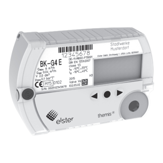
ATEX Checking the usage ▷ The electronic index is suitable for use in potentially Electronic index EI.00, EI.05, EI.06, explosive atmospheres. For the exact use (zone), EI. for diaphragm gas meters BK-G...E, see ATEX sticker on the diaphragm gas meter or BK-G...ET or BK-G...ETe see the operating instructions for diaphragm gas Electronic index for reading out absolute meter read-... -
Page 3: Navigating Within The Menu
User keys, selection key and symbols Menu overview ▷ You can navigate through the menu using the The display can differ depending on the parameteriza- tion or communication module. user keys and the selection key . Symbol Meaning Navigate to the left or the right on each level using the user keys. - Page 4 Date and time Electronic index with communication module: ▷ Information on the date and time display. ▷ The symbol is displayed if, for example, the tolerance between the internal time recording Date and time and the actual time is too large. This can lead 2011 to invalid consumption data.
-
Page 5: Service Mode
Service mode menu overview Service mode Part designations Test instructions 5 6 7 8 B K -G x 1 2 3 4 TB 00 1 Temperature (optional) -M I00 2-P DE -07 ma x M 07 01 63 27 34 00 25 45 Battery diagnosis Date &... - Page 6 – [ ] max. allowable gas temperature range Date and time ▷ Information on the date and time display. [min. value, max. value] – tsp: specified centre temperature t (in ac- Date and time cordance with EN 1359) 2011 – base temperature t (in accordance with –...
-
Page 7: Establishing An Optical Communications Link
▷ If the optical communications link is not used where T = (273.15 + {t }) K = (273.15 + {t }) K during this time, the interface will be deactivated. is specified in the technical data, see page Initiate communication. ▷... -
Page 8: Setting The Index Parameters
APPLIANCES OFF CHECK IF HOLD FOR GAS ▷ After a short time, the unit switches to initializa- 4 Reprogram the battery parameters. APPLIANCES OFF ▷ The procedure depends on your user software. tion mode. Electronic index without communication module: Opening valve Gas o ▷... -
Page 9: Module
Replacing the communication module Retrofitting/replacing the Establish the optical communications link, see communication module page 7 (Establishing an optical communica- tions link). WARNING Deactivate the respective communication mod- Risk of explosion in explosion-hazard areas! ule. – As a general rule, maintenance and repair work should be avoided in explosive atmospheres. - Page 10 ▷ To conduct the tests, the thermowell and the Option : cyclic test at a constant flow rate ▷ The test rig is in pre-trial operation, i.e. start of pressure test point (if available) can be used as a reference for the temperature and pressure measurement on the unit under test will be de- measured by the meter.
- Page 11 ▷ Once the required minimum testing time has Option : cyclic test with a given volume been reached, the measurement can be termi- Test load and minimum test volumes for the test with nated – marker 4. index readout: 4 Briefly press the selection key in order to end Cyclic Test volume in dm...
- Page 12 ▷ The following also applies: Pulse test at a constant flow rate (optical interface) for BK-G…E: T = (273.15 + {t }) K Master meter test procedure where t = relevant gas temperature on the unit under test in °C (display) for BK-G...ET: T = (273.15 + {t }) K...
- Page 13 The accuracy is checked by comparing the flow 8 Determine the volume on the unit under test V rates. The pressure and temperature values of = N x V the unit under test corrected with reference to = number of pulses the master meter have already been taken into = pulse value in m³...
-
Page 14: Assistance In The Event Of Malfunction
Temperature test • Leave the index unused for an extended period, ▷ A temperature test is required on diaphragm gas e.g. 24 hours. After this, the user interface will meters with temperature conversion BK..Te only. once again be available. ▷ The accuracy of the temperature measurement can be verified with this test. -
Page 15: Technical Data
Technical data Logistics Application with diaphragm gas meters BK..E Transport RoHS compliant Diaphragm gas meters are always to be transported Enclosure: IP 54. in the upright position. On receipt of the product, Battery life: approx. 10 years. check that the delivery is complete, see page 2 Maximum allowable ambient temperature range: see (Part designations). -
Page 16: Contact
Contact Contact United Kingdom Elster Metering Limited Paton Drive Tollgate Business Park Beaconside Stafford, ST16 3EF Tel. +44 1785 275200 Fax +44 1785 275305 jeavons.info@gb.elster.com www.elstermetering.co.uk Ireland Germany Active Energy Control Ltd. Elster GmbH Unit 4, Clare Marts Strotheweg 1 Quin Road 49504 Lotte Ennis, Co.
Need help?
Do you have a question about the Themis alpha EI2 and is the answer not in the manual?
Questions and answers