Advertisement
Quick Links
TrendView recorders - Installation Instruction
Analogue In / Analogue Out / Pulse Input cards / Alarm Relay
and Digital Input / Output cards
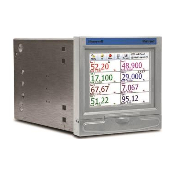
Minitrend Recorder Multitrend Recorder
This Installation Instruction sheet is intended as a guide for replacing or installing hardware and for setting up
functionality in the recorder. Refer to the User manual for detailed operational requirements.
The Minitrend, Multitrend, eZtrend and DR Graphic recorders are designed for ease of assembly with minimal
disturbance to the rest of the unit. If unsure, please return the unit to your supplier for repair or upgrade.
Removing the case and opening the back of the recorder should only be performed under the following circumstances:
When an item of hardware requires individual replacement.
When an item of hardware is to be retrospectively fitted.
In all other instances, it is recommended that the complete unit be returned to an authorised agent or service centre.
For Agency Approved recorders the product needs to be upgraded or repaired by an Authorized Repair facility.
WARNING
HAZARDOUS VOLTAGES
Disconnect all power to the recorder before removing the case and attempting any maintenance procedures.
For DR Graphic Recorders: Disconnect all the power, CJCs and IO cabling to the recorder before removing the IO cards
chassis or power supply chassis and attempting any maintenance procedures.
SAFETY TESTS
Upon completion of service procedures detailed in this manual two basic safety tests should be performed in order to
ensure continued safe operation of the instrument.
Failure to comply with these instructions could result in death or serious injury.
CAUTION
OBSERVE ANTI-STATIC PRECAUTIONS
Refer to BS EN61340-5-1: 2001. Basic specification. Protection of electrostatic sensitive devices.
Full anti-static precautions MUST be observed when in contact with the electronics of your recorder.
SAVE DATA, SETUPS AND LAYOUTS
Removal of PCBs and battery back-up will result in the loss of all non-volatile data.
Ensure all data and set-ups are saved.
Failure to comply with these instructions may result in product damage.
Before attempting to repair or upgrade a recorder, it is advisable to clear a sufficient work space so components such as
the front panel can be rested on the work surface without getting scratched or damaged.
If adding a new piece of hardware to your recorder please be aware that if you are running Trend Manager PC software
that the "Hardware Wizard" will require updating to accommodate the hardware changes.
43-TV-33-56 iss.4 GLO Aug 19 UK
eZtrend Recorder
DR Graphic
Recorder
1
Advertisement

Related Manuals for Honeywell Minitrend


Summary of Contents for Honeywell Minitrend
- Page 1 Refer to the User manual for detailed operational requirements. The Minitrend, Multitrend, eZtrend and DR Graphic recorders are designed for ease of assembly with minimal disturbance to the rest of the unit. If unsure, please return the unit to your supplier for repair or upgrade.
- Page 2 Removal of the rear panel is necessary for replacement or fitting any of the PC cards. To remove the rear panel of the recorder, loosen and remove the two screws (Minitrend and eZtrend = M3 x 6, Multitrend = M4 x 8) at the top corners of the rear panel, taking care to retain both the shake-proof washer and the screw.
- Page 3 Figure 2 - Minitrend recorder Minitrend Cards Position Shown Card Type Slot Power Supply Card Transmitter Power Supply Card Analogue Input Card A, B Pulse Input Card A, B Analogue Output Card B (Not shown) Alarm/Digital IO Card Processor Card...
- Page 4 (Only 6 channel boards are available for the eZtrend recorder) An Analogue Input card can be fitted in slots A to F of an Multitrend recorder, slots A and B on a Minitrend recorder or slot B on a eZtrend recorder.
- Page 5 The Pulse Input Card is only available as a 4 channel card. A Pulse Input card can be fitted in slots A to F of an Multitrend recorder, or slots A or B on a Minitrend recorder. (Not available for the eZtrend recorder) The card has a 12 way connector and a blanking plate, which is fitted to the left of the connector.
- Page 6 The Digital I/O cards are available with 8 or 16 channels; all channels may be used as digital inputs or relay outputs. (Only the 8 channel version is available on eZtrend) All alarm cards take up slot position in slot G in the Minitrend and eZtrend recorders and slot positions G, H and I in the Multitrend recorder.
- Page 7 NOTE: To add an Analogue input board to the eZtrend recorder the recorder must already have an Expansion board fitted. If the Expansion board is fitted continue as described below, if an Expansion Board has to be fitted refer to Instruction sheet 43-TV-33-81 “eZtrend Expansion Board”. Minitrend and Multitrend recorders will always have a Mother Board already fitted.
- Page 8 If the alarm card is being replaced, locate and remove the M3 x 8 earth screw from the bottom position of the unit, (Minitrend and eZtrend = Slot G, Multitrend = Slot G, H and I) see Figure 13, 14 and 15.
-
Page 9: Re-Assembling The Unit
Reposition the shake-proof washers and replace and tighten two screws (Minitrend and eZtrend = M3 x 6, Multitrend = M4 x 8) at the top corners of the rear panel. - Page 10 3. Remove the slant chassis plate on the back side of the IO card chassis. Figure 18 Cabling inside the slant chassis plate 4. Lift the IO card chassis from the front side and park it on the bottom stand. See Figure 19.
- Page 11 6. For installing the new card in an empty slot (A or B or both), remove the front panel screws. See Figure 20. For replacing cards in Slot A, remove both the front panel screws along with the Slot A screw. ...
- Page 12 Removing IO cards Once the side screws on the earth brackets are removed, the IO cards can be easily pulled out of the IO card chassis for replacement. Inserting IO cards The DR Graphic recorder has the backplane card fitted inside the IO Card Chassis along with the CPU card. Cards can be inserted into the IO card chassis through the horizontal guides present inside the IO card chassis as per the combinations mentioned in the table DR Graphic...
- Page 13 Re-assembling the Unit After IO cards are removed, replaced or added to the recorder, use the following procedure to re-assemble the unit. 1. Make sure to secure all the IO cards and backplane card tightly with the earth bracket using M3 X 8 screws from the side of the IO card chassis as shown in Figure 23.
- Page 14 Figure 25 - Cables to be connected inside slant chassis plate to the CPU board 3. Lift the IO card chassis; fold back the bottom stand inside and keep the IO card chassis back into the case for reconnecting the different cables. Connectors of all the cables are polarized;...
- Page 15 4. Connect all the cables as per the information in the above table and by using Figure 26. Figure 26 Cables reconnected inside the slant chassis plate 5. Replace the slanted chassis plate and fit it back along with the earth braid using 2x No.4/40 screws as shown in Figure 27.
- Page 16 6. Make sure all the screws shown in red and green colours in Figure 28 are connected back. Figure 28 Reconnecting the IO cards chassis 7. Reconnect the CJCs, IO cabling and Power cable as required. 8. Close the door. 9.
Need help?
Do you have a question about the Minitrend and is the answer not in the manual?
Questions and answers