Table of Contents
Advertisement
Quick Links
Advertisement
Table of Contents

Related Manuals for Honeywell Class 320 Meter


Summary of Contents for Honeywell Class 320 Meter
- Page 1 Class 320 Meter ADVANCED KWH/DEMAND METER INSTALLATION INSTRUCTIONS 62-0397-02...
-
Page 2: Table Of Contents
Safety Label Definitions and Information Section 5.0 Precautionary and Safety Information Section 6.0 Meter Installation Section 6.1 Mounting the Class 320 Meter Section 6.2 Main Power Board Connections Section 6.3 Phasing of Line Voltage Section 6.4 Current Sensor Installation & Wiring Section 6.5... -
Page 3: Introduction
600V 600V, Three Phase Verify that the Class 320 meter’s current sensors are sized suitably for the load to be monitored. Compare the color of the arrows on the current sensors to the chart below to confirm the correct current sensor is being used. - Page 4 WARNING Use of this instrument, the Honeywell Class 320 meter, in a manner inconsistent with this manual or not specified by the manufacturer in writing, can cause permanent damage to the unit and/or serious injury to the operator.
-
Page 5: Internal Electronic Assemblies
CLASS 320 METER 2.0 INTERNAL ELECTRONIC ASSEMBLIES The units are comprised of two major subassembly boards, the main power board and the display board. Both circuit boards are mounted inside a UL Type 1 (steel) or Type 4X (rain tight) enclosure. -
Page 6: Display Board
The display board connects to the main power board via a flex ribbon cable and the board mounts on the inside of the housing door. The Class 320 meter features a 4-line LCD display that indicates multiple meter data points. -
Page 7: Meter Technical Specifications
Ordering Information: Define brand, class, input voltage, amperage, protocol, and sensor type in the format A-BB-CCC-DDDD-E-FFF-GGG, where: A = Brand: H for Honeywell BB = designates Class 320 (32), or Class 500 (50) meter CCC = input voltage: (208, 400, 480, 600, 120 volt for High Voltage) - Page 8 CLASS 320 METER Temperature Range -20C to +50C Relative Humidity 0-95% non-condensing Range Altitude 2000 meters maximum Voltage Overload +25% continuously: +100% For 20 cycles Current Sensor 100% for 1 minute Overload Pollution Degree Degree 2 in accordance with IEC 664...
- Page 9 CLASS 320 METER Battery Cell: Description: Non-rechargeable cell used for memory retention Manufacturer: Panasonic Mfg Part No: CR2032 Working Voltage: 3Vdc Current Capacity 225 mAHr Electrolyte: Manganese Dioxide Lithium 62-0397-02...
-
Page 10: Safety Label Definitions And Information
CLASS 320 METER 4.0 SAFETY LABEL DEFINITIONS AND INFORMATION The 320 meter may contain one or more of the following labels. Operator(s) should familiarize themselves with the meaning of each label to minimize risk. Notice This equipment has been tested and found to comply with the limits for a Class B digital device, pursuant to part 15 of the FCC Rules. -
Page 11: Precautionary And Safety Information
CLASS 320 METER 5.0 PRECAUTIONARY AND SAFETY INFORMATION CAUTION Internal circuit card components are extremely sensitive to electrostatic discharge. Be careful not to touch internal circuitry prior to discharging any static buildup on your person. To discharge yourself, touch a grounded metal object such as conduit or an earth-grounded metal enclosure. -
Page 12: Meter Installation
CLASS 320 METER 6.0 METER INSTALLATION 6.1 Mounting the Class 320 Meter 6-35/64 (166) 5/8 (16) 6-35/64 (166) 7-51/64 (198) Ø 1-3/32 (28) THROUGH 3-17/64 (83) NEAR SIDE ONLY 3-25/64 (86) 1-5/8 (41) M34684 Fig. 4. Meter Dimensions. Use appropriately sized mounting hardware to fasten the Class 320 enclosure to the selected mounting surface. -
Page 13: Main Power Board Connections
CLASS 320 METER 6.2 Main Power Board Connections 1. Installing a temporary ground for ESD protection: With all circuits de-energized, connect a temporary protective earth ground connection for ESD protection. Prior to performing any unit wiring, be sure to discharge any static on your per- son. - Page 14 Connect the Earth Ground to the PCB mounting screw in lower right corner. C. External Switch Mechanism/In-Line Fuse Installation To ensure a safe installation, the Class 320 meter requires an external switch mechanism, such as a circuit breaker, be installed on the meter’s MAINS input wiring.
- Page 15 CLASS 320 METER 6.2 Main Power Board Connections (continued) D. Connect the three AC main power wires (Phases A, B and C) to their respec- tive positions as labeled on terminal block TB1. After all conductors are con- nected to each of their respective terminal block positions and tightened to 7 in-lb, verify that each terminal block screw is securely fastened by gently tug- ging on each conductor.
-
Page 16: Phasing Of Line Voltage
CLASS 320 METER 6.3 Phasing of Line Voltage The 3-phase AC power input or single phase option must be in proper phase sequence. If the sequence is incorrect or a phase is missing, there will be a message on the meter’s display: “PH Sequence Error” or “PH Missing:. (Refer to the section on Line Voltage Diagnostics if this message is present.) When the line voltage is... -
Page 17: Current Sensor Installation & Wiring
CLASS 320 METER 6.4 Current Sensor Installation & Wiring Once the AC voltages have been confirmed to be within acceptable limits, you are ready to install the current sensors. TB2 is the input for Phase A, TB3 is the input for Phase B and TB4 is the Phase C input. - Page 18 To do this, there must be at least 1% of the meter’s current rating (amps) flowing in each of the conductors being monitored. The Class 320 meter’s diagnostic program (on the 4-line display) will provide data to ensure that the current sensor installation is done properly.
-
Page 19: Main Power & Current Sensor Wiring Diagram
CLASS 320 METER 6.5 Main Power & Current Sensor Wiring Diagram LINE VOLTAGE CURRENT SENSORS 3-PHASE, 4-WIRE INSTALLATION DIAGRAM NOTES: LINE VOLTAGE CONNECTIONS: #14-22 AWG SENSOR CONNECTIONS: B = BLACK LEAD W = WHITE LEAD NEUTRAL NOT USED IN DELTA SYSTEM. REMOVE NEUTRAL TERMINAL BLOCK SCREW FOR DELTA SYSTEMS. -
Page 20: Line Voltage/Current Sensor Diagnostics
CLASS 320 METER 6.6 Line Voltage/Current Sensor Diagnostics Following is a list of diagnostic messages that may appear on the meter display. DIAGNOSTIC MESSAGES SHOULD NOT BE ON CONTINUOUSLY WHEN THE METER IS INSTALLED PROPERLY AND IS IN WORKING ORDER. -
Page 21: Rs-485 Wiring
CLASS 320 METER 6.6.2 Current Sensor Diagnostics The load current must be at least 1% of the meter’s rated load in order to use the diagnostic function. Current sensor diagnostics can detect: 1. Reversed current sensors 2. Incorrect phase correspondence 3. - Page 22 CLASS 320 METER 6.7 RS-485 Wiring (continued) * An alternate version of firmware is available that replaces Modbus RTU with BACnet The meter must be ordered with this option if BACnet is desired instead of MS/TP. Modbus. There are two connection methods, daisy-chain and wire terminal, for RS-485 communications.
- Page 23 6.7 RS-485 Wiring (continued) 6.7.1 RS-485 Bias Resistors When interfacing the Class 320 meter to certain RS-485 communication equipment, it may be necessary to add bias resistance to the circuit. If this is required, there is a 2- position DIP switch on the meter’s door mounted (display) circuit board. With both positions in the “ON”...
-
Page 24: Rs-232 Communications
6.8.1 Hardwired System using the RS-232 Communication Key The RS-232 communications key allows you to connect Class 320 meters to a personal computer that has the Honeywell Energy™ software installed. The computer communicates with the meters through the RS-232 key. - Page 25 NOTE: When the Honeywell Energy™ software is accessed on the computer, a third LED (RS232 READY) will turn on. This indicator will light up as soon as the Honeywell Energy software is booted up and the correct COM port is set up via the settings provided in the software’s Locations menu.
-
Page 26: Modem Wiring
CLASS 320 METER 6.9 Modem Wiring UP TO 4000 RS-232 SERIAL FEET TOTAL PORT COM1 THROUGH COM3 UP TO 52 MAXIMUM 15 FEET CLASS 3200 CHANNEL 1 METERS PER CHANNEL LOCAL MODEM RS-232 CHANNEL 2 KEY RM PC OR WINDOWS... - Page 27 CLASS 320 METER 6.9.1 Modem (RS-232 KEY RM) The RS-232 key with modem connects the entire RS-485 network of Class 320 meters to a telephone line. ** Refer to Section 6.7 for RS-485 network connections. On the back panel of the RS-232 key/modem, the left jack (RS232) is not used in most cases since there is no local host computer.
- Page 28 6.9.3 Baud Rate Selection The communication Baud rate on the Class 320 meter is set through positions 3 and 4 on DIP switch S2 on the meter circuit board. The default is 9600 Baud. 1. Select 9600 when using the Class 320 meter with a modem.
-
Page 29: Modbus Rtu Wiring
CLASS 320 METER 6.10 Modbus RTU Wiring The Class 320 Modbus option meter communicates with building automation equipment over a 2-wire (3-conductor) RS-485 network using Modbus RTU protocol. The meters are networked in a daisy-chain configuration with BELDEN 1120A cable or equivalent required. -
Page 30: Bacnet Ms/Tp Wiring
CLASS 320 METER 6.11 BACnet MS/TP Wiring BACnet MS/TP wiring is the same as Modbus and EZ7 wiring. See Sections 10 and 11 for instructions on changing I.D. and IP addresses. 6.12 Connecting Class 320 Meters to USB Key using RS485 The USB Key plugs into the PC’s USB port and provides a termination point for the... -
Page 31: Ethernet Communications
Each device (EKM-E) that is connected directly to the ethernet network requires a unique IP address. With a public IP address, the system can be addressed with Honeywell Energy software through the internet for remote reading capabilities. EKM-E RS-485 DAISY CHAIN (SECTION 6.7) -
Page 32: Multiple-Load Monitoring
CLASS 320 METER 7.0 MULTIPLE-LOAD MONITORING The Honeywell Class 320 meter provides extreme flexibility by allowing additional sets of current sensors to be used in parallel so multiple load locations can be monitored by one meter. This feature allows a totalized display readout from two or more load circuits. -
Page 33: Preventative/Scheduled Maintenance
CLASS 320 METER 7.0 MULTIPLE-LOAD MONITORING (CONTINUED) NOTE: One set of current sensors equates to three sensors, one per phase. The multiplier only applies when extra sets of current sensors are installed on one meter. If you are using only one set of three current sensors, the multiplier is not required. -
Page 34: Lithium Battery Replacement
CLASS 320 METER 9.0 LITHIUM BATTERY REPLACEMENT The Class 320 meter has a lithium coin cell battery, which is used to retain the contents of SRAM and the RTC during power outages. The battery’s life expectancy is greater than 5 years. - Page 35 CLASS 320 METER 9.0 LITHIUM BATTERY REPLACEMENT (CONTINUED) Use the following procedure to replace the lithium battery cell. CAUTION The battery is not completely discharged; therefore, DO NOT short the terminals on the battery with any conductive material. CAUTION Internal circuit card components are extremely sensitive to electrostatic discharge.
-
Page 36: Class 320 Meter Operating Modes
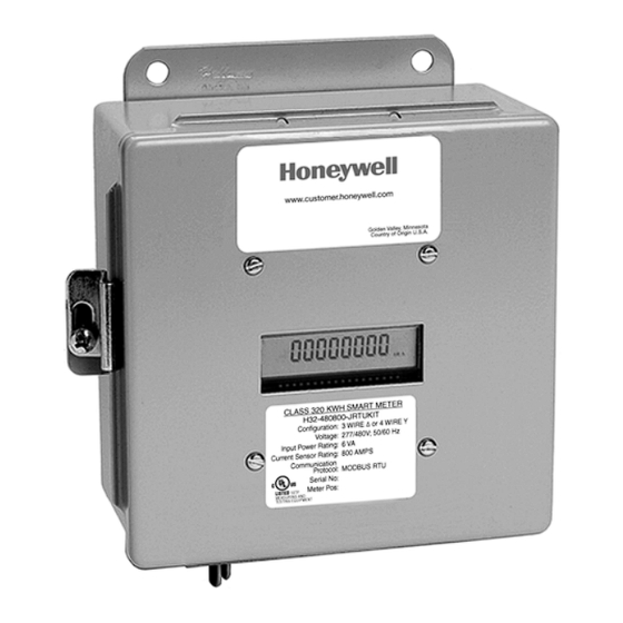
10.0 CLASS 320 METER OPERATING MODES The Honeywell Class 320 meter is used to monitor electric power usage of individual loads after the utility meter and store kW and kVAR data for automatic meter reading. Fig. 24. Class 320 Stand Alone Meter with 4 Line Display. -
Page 37: Normal Mode Display Screens
CLASS 320 METER 10.2 Normal Mode Display Screens The Class 320 meter features seven Normal Mode Display Screens for monitoring the meter. Each screen is displayed for 5 second intervals, before scrolling onto the next screen. You can “lock” the scrolling display on any one of the seven screens. This will be explained in detail on following pages. -
Page 38: How To Program The Display Screens
CLASS 320 METER DOWN MENU SELECT M33279 Fig. 27. Push Buttons. 10.3 How to Program the Display Screens The display information can be programed using four push buttons switches. The push buttons (DOWN, UP, SELECT, MENU) are located at the bottom of the display board on the inside front door of the meter. - Page 39 CLASS 320 METER 10.3.1 Date & Time To change the date and time, complete the following steps: 1. Press the MENU button. 2. The following screen will appear: Date & Time Device ID Reset KW/KWH Read Exit 3. Press the SELECT button. The date and time screen will appear, and the 2 digit month will be blinking.
- Page 40 CLASS 320 METER 10.3.2 Device I.D. To change Device I.D., complete the following steps: 1. Press the MENU button. 2. The following screen will appear: Date & Time Device ID Reset KW/KWH Read Exit 3. Use the UP and DOWN buttons to select the Device ID line.
- Page 41 CLASS 320 METER 10.3.3 Peak Demand Reset To reset the recorded peak kW demand, complete the following steps: 1. Press the MENU button until “Reset kW/kWh Read” is indicated by the arrow on the display. Date & Time Device ID...
- Page 42 CLASS 320 METER 10.3.4 Display Hold Feature You can “lock” the scrolling display so that it will stay locked on any one of the seven screens. To stop the display from scrolling, complete the following steps: 1. Press the UP and DOWN buttons to choose which of the six screens you would like to display.
-
Page 43: High Voltage Metering
CT secondary is installed as a continuous “loop”, with a single conductor connected to both secondary terminals. To convert the 0~5 amp signal to a 0~ 2 volt signal, Honeywell’s Current Sensors are installed on the CT secondary conductor. A set of 25 amp sensors is used in this application. - Page 44 CLASS 320 METER PASS PASS PASS PASS PASS M34227 Fig. 28. High Voltage CTs. M34228 Fig. 29. Wiring Diagram For 3-wire High Voltage Circuits. 62-0397-02...
- Page 45 High voltage PTs reduce the primary voltage (4160v, 13200v, etc.) to a Secondary output of 120v. This secondary is connected to the Honeywell meter voltage inputs as shown in the wiring diagram. High voltage CTs reduce the primary current (amps) to a directly proportional 0~5 amp output.
-
Page 46: Class 320 Protocol Definitions
CLASS 320 METER 12.0 CLASS 320 PROTOCOL DEFINITIONS ModBus Customer Point Map: CL320 Address Registers Format Description Units Integer Energy delivered Wh Pulse 40001 Integer Energy received Wh Pulse 40001 Integer Reactive energy delivered VARh Pulse R/W 40005 Integer Reactive energy received... - Page 47 CLASS 320 METER ModBus Customer Point Map: CL320 Address Registers Format Description Units 41033 Float Real power, phase C 41035 Float Reactive power, phase A kVAR 41037 Float Reactive power, phase B kVAR 41039 Float Reactive power, phase C kVAR...
- Page 48 CLASS 320 METER ModBus Customer Point Map: CL320 Address Registers Format Description Units Custom Interval Day Block 44001 1 per Integer Interval Data Pulse 44007 interval 2 per day Custom Interval Data Headers 45501 Custom RTC Date/Time 46025 Custom EZ7 ID, ModBus ID, Serial Number...
- Page 49 CLASS 320 METER BACnet Object Descriptors: CL320 Instance BACnet BACnet Object Description Units Property Analog Energy delivered Present Value R Input Analog Energy received Present Value R Input Analog Reactive energy delivered kVARh Present Value R Input Analog Reactive energy received...
- Page 50 CLASS 320 METER BACnet Object Descriptors: CL320 Instance BACnet BACnet Object Description Units Property Analog Reactive power phase C kVAR Present Value R Input Analog Apparent power phase A Present Value R Input Analog Apparent power phase B Present Value R...
- Page 51 CLASS 320 METER BACnet Object Descriptors: CL320 Instance BACnet BACnet Object Description Units Property Analog Reserve A No units Present Value R Input Analog Reserve B No units Present Value R Input Analog Reserve C No units Present Value R...
- Page 52 CLASS 320 METER Instance ID BACnet Object BACnet Property CL320 BACnet Device ID Device Object identifier BACnet Device ID Device Object name BACnet Device ID Device Object type BACnet Device ID Device System status BACnet Device ID Device Vendor name...
- Page 53 2. Honeywell must be notified of the defect within ninety (90) days after the defect becomes apparent or known. 3. Buyer’s remedies shall be limited to repair or replacement of the product or com- ponent which failed to conform to Honeywell’s express warranty set forth above.
- Page 54 CLASS 320 METER 62-0397-02...
- Page 55 CLASS 320 METER 62-0397-02...
- Page 56 CLASS 320 METER Automation and Control Solutions Honeywell International Inc. 1985 Douglas Drive North ® U.S. Registered Trademark Golden Valley, MN 55422 © 2013 Honeywell International Inc. 62-0397-02 JPG Rev. 07-13 customer.honeywell.com Printed in United States...
Need help?
Do you have a question about the Class 320 Meter and is the answer not in the manual?
Questions and answers