Table of Contents
Advertisement
Quick Links
Advertisement
Table of Contents

Related Manuals for Sachtler S2051-0001


Summary of Contents for Sachtler S2051-0001
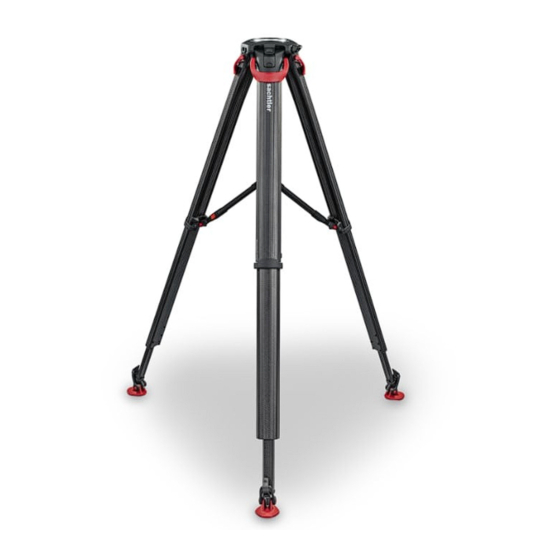
- Page 1 User Guide Tripod Part No. S2051-0001 S2052-0001 www.sachtler.com...
- Page 2 All other trademarks and registered trademarks are the property of their respective companies. Published by: Vitec Production Solutions Supports Technical Publications Department Email: technical.publications@vitecgroup.com Other languages available DE. For download please visit www.sachtler.com/flowtech Video tutorials are available, if required please contact support@vitecgroup.com for further details.
-
Page 3: Table Of Contents
Contents Safety........2 Accessories ......18 Fit Supplied Attachment Mount . -
Page 4: Safety
Safety Important information on the safe installation and operation of WARNING! Trip hazard. Set the tripod footprint to suit the the product. Read this information before operating the product. shooting environment. For your personal safety, read these instructions. Do not operate the product if you do not understand how to use it safely. -
Page 5: About This Guide
The tripod is improperly installed or used in a manner contrary to this user guide. • The tripod housing is opened by unauthorised personnel. We reserve the right to make changes to the product based on technological advances. Extended warranty Please register at www.sachtler.com for an extended warranty period. -
Page 6: Operating Elements
Operating Elements Pos No. Description Hinge Lock Slider Hinge Lock Button Double-spiked Foot Leg Magnetic Clasp Quick Release Lever Accessory Dock x 3 Attachment Mount... -
Page 7: Optional Accessories
Optional Accessories Pos No. Description Part No. S2051-1073 Rubber Feet Mid-level Spreader flowtech 75 S2054-1001 Mid-level Spreader flowtech 100 S2056- 0001 S2051-1900 Attachment Mount Carry Strap Kit 8691 Carry Handle c/w Hex Key S2051-1057 S2058-0001 Ground Spreader... -
Page 8: Installation
Installation Setting up the Tripod With the correct height achieved, lower the quick release levers to lock the legs in position. The legs are secured using magnetic catches. Pull the legs from the bottom to separate. Note! If preferred this step may be performed after step 3. WARNING! The legs are only sufficiently locked when the locking levers are in the fully closed (down) position. -
Page 9: Attach Optional Mid-Level Spreader
Installation Attach Optional Mid-Level Spreader flowtech 75 Unlock the spreader arms to allow the arms to extend as required. Tighten the spreader locks when the tripod legs are in the correct CAUTION! Ensure the latching pins are fully engaged with position. -
Page 10: Attach Optional Mid-Level Spreader Flowtech 100
Installation Attach Optional Mid-Level Spreader flowtech 100 flowtech 100 Operation of Mid-Level Spreader Press and hold the arm release button (as below). CAUTION! Ensure the latching pins are fully engaged with the locating holes in the tripod. Failure to attach correctly Extend the inner arm to the required length and release the could result in damage to the equipment button. - Page 11 Installation The spreader has 4 x locking positions 50, 40, 30 and 0° Rotate the adjustment cap on top of the spreader, anticlockwise to allow the spreader to open to the selected setting. A positive click will be felt as each position is achieved. 50°...
-
Page 12: Attach Optional Ground Spreader Flowtech
Installation Attach Optional Ground Spreader flowtech 75 / 100 Place the spreader flat on the floor. CAUTION! Ensure the ground spreader legs are all the same length before attempting to fold the tripod with the spreader attached. Failure to observe this procedure could lead to damage of the Ground Spreader The tripod is delivered with the Hinge Lock in the OFF position for use with a spreader. -
Page 13: Operation Of Ground Spreader
Installation Operation of Ground Spreader Bend the rubber strap and engage the bottom edge of the When assembled on the tripod, use your foot to press and hold lever in the tripod recess. the arm release button (as below). Lift the lever upwards towards the tripod until it locks in place. - Page 14 Installation Closing Tripod with Ground Spreader Attached To close the tripod legs, ensure all the spreader legs are set at the same distance. Lift the spreader using the centre knob, then close the legs as normal. CAUTION! Ensure the ground spreader legs are all the same length before attempting to fold the tripod with the spreader attached.
- Page 15 Installation Remove Foot from Spreader To remove the feet from the spreader, push the foot release button towards the centre of the spreader. Lift the foot from the spreader. Reverse the procedure to re-attach the feet to the spreader Cleaning. After each use, brush off any dirt or debris, if necessary wash down The spreader can be removed from the feet while they are still attached to the tripod...
-
Page 16: Using Locks When No Spreader Used
Installation Using Locks When no Spreader Used No Spreader Mode With the lock in the raised position the lock is ON. The tripod can be used without a spreader using the three Hinge Lock Slider in the engaged lock positions. (ON) position. -
Page 17: Opening Tripod Legs
Installation Opening Tripod Legs The angle of each leg can be adjusted independently of the The first position at 20° is likely to be the most used position. other two legs. To select the 46° or 72° position, disengage the lock. Press the lock button to engage the lock. - Page 18 Installation Continue pulling the leg until it stops at the 46° lock position. Move the leg past the 20° position. Engage the Lock Slider by pushing the Hinge Lock Button. 46° Repeat procedure for the 72° position. 72° Repeat for the remaining legs as required.
-
Page 19: Alternative Locking Method
Installation Alternative Locking Method WARNING! Risk of finger entrapment. Avoid trapping fingers when operating the tripod. An alternative method would be to release the Hinge Lock, and fully open the leg to 90° Move the leg towards the body. As the leg passes each lock point, an audible click will be heard, the leg is prevented from opening past this point again without disengaging the lock first. -
Page 20: Close Tripod Legs
Installation Accessories Fit Supplied Attachment Mount Close Tripod Legs There are three accessory docks. These can be used to dock the The legs may be closed with or without the Lock being engaged. supplied attachment mount, optional handle or a Magic Arm etc.. Ensure the tripod legs are fully collapsed before moving them Offer the accessory to the docking point on the tripod head. -
Page 21: Fit Optional Carry Strap
Accessories Attach Optional Rubber Feet Fit Optional Carry Strap Place the rubber foot between the spikes. Check the marking on Fit the attachment mount as previous section: “Fit Supplied the foot for the correct orientation. The ‘flowtech’ marking must Attachment Mount”. face outwards. -
Page 22: Fit Carry Handle (S2051-1057)
Accessories Maintenance Cleaning Fit Optional Carry Handle (S2051-1057) To attach the handle to one of the accessory docks. Video tutorials are available, if required Using a fingernail or small screwdriver, lever the rubber sleeve please contact support@vitecgroup.com away from the top of the handle to reveal the (pre installed) for further details. -
Page 23: Hinge Lock Cleaning
Maintenance Hinge Lock Cleaning Lift out the hinge lock button. The Hinge lock is designed so that sand or other debris may be worked out of the hinge lock mechanism. Repeatedly operate the button and hinge slider, combined with blowing out the debris until the mechanism operates smoothly. Should this procedure fail to sufficiently clear the debris, follow the instructions below to disassemble the mechanism for cleaning. -
Page 24: Checking Brake Force
19 20 21 22 23 24 25 26 27 28 29 30 31 please contact your local service centre. adjustment is required. flowtech 100 “See Adjusting brake force”. www.sachtler.com 29 30 31 32 33 34 35 36 37 38 39 40 41 Average slip force... -
Page 25: Friction Adjustment
Maintenance Leg Friction Adjustment Should the leg friction require adjustment, open the legs to gain access to the M5 friction screws on the underside of the tripod. The correct torque for these M5 screws is 2.5Nm to 3.5Nm Max. Use a torque screwdriver to adjust the M5 screws to the correct torque. -
Page 26: Specification
Technical Specification 75 mm 100 mm 75 mm 100 mm Tripod Tripod Tripod Tripod Maximum Operational 157 cm 155 cm Bowl 75 mm 100mm Height (61.81 in.) (61.00 in.) On Mid-Level Spreader Minimum Operational 20 kg 30 kg 52 cm 63 cm Maximum payload Height... - Page 28 Publication No. S2051-4983/3 www.sachtler.com...
Need help?
Do you have a question about the S2051-0001 and is the answer not in the manual?
Questions and answers