Sign In
Upload
Download
Table of Contents
Contents
Add to my manuals
Delete from my manuals
Share
URL of this page:
HTML Link:
Bookmark this page
Add
Manual will be automatically added to "My Manuals"
Print this page
×
Bookmark added
×
Added to my manuals
Manuals
Brands
Sachtler Manuals
Camera Accessories
aktiv6
User manual
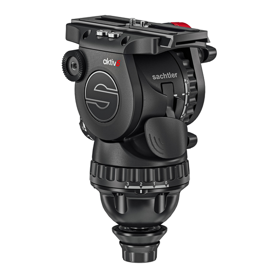
Sachtler aktiv6 User Manual
Fluid head
Hide thumbs
1
2
Table Of Contents
3
4
5
6
7
8
9
10
11
12
13
14
15
16
17
18
19
20
21
22
23
24
25
26
27
28
29
30
31
32
33
page
of
33
Go
/
33
Contents
Table of Contents
Bookmarks
Table of Contents
Table of Contents
Safety
About this Guide
Intended Use
About this User Guide
Warranty
Extended Warranty
Serial Number Location
Box Contents
Optional Speedswap Accessories
Operating Elements
Left View
Right View
Prismbubble
1St Time Installation
Fitting Bowl Connector for the 1St Time
Mounting Head and Setting Connector Tension
Operation
Attaching, Levelling, Removing Head
Dismounting the Fluid Head
Mounting, Dismounting the Camera (Touch and Go)
Mounting, Dismounting the Camera (Sideload)
Fitting the Pan Bar
Adjusting the Pan Bar
Configuring the Pan Bar
Balancing the Payload
Adjusting the Centre of Gravity (C of G)
Additional C of G Adjustments
Adjusting the Counterbalance
Adjusting the Drags
Transportation Head Settings
Transporting with the Pan Bar
Maintenance
Technical Specification
General Notices
Advertisement
Quick Links
1
Fitting Bowl Connector for the 1St Time
2
Attaching, Levelling, Removing Head
3
Transportation Head Settings
4
Maintenance
Download this manual
User Guide
aktiv6, aktiv8, aktiv8T, aktiv10 Fluid Head
EN
S2064S
aktiv6
S2068S
aktiv8
S2068T
aktiv8T
S2072S
aktiv10
www.sachtler.com
Table of
Contents
Previous
Page
Next
Page
1
2
3
4
5
Advertisement
Table of Contents
Need help?
Do you have a question about the aktiv6 and is the answer not in the manual?
Ask a question
Questions and answers
Related Manuals for Sachtler aktiv6
Camera Accessories Sachtler aktiv10 User Manual
Fluid head (36 pages)
Camera Accessories Sachtler Ace Follow Focus Manual
(12 pages)
Camera Accessories Sachtler Ace Follow Focus Manual
(64 pages)
Camera Accessories Sachtler Artemis DV Manual
Camera stabilizing system (23 pages)
Camera Accessories Sachtler Ace Matte Box Manual
(88 pages)
Camera Accessories Sachtler aktiv8 User Manual
Fluid head (33 pages)
Camera Accessories Sachtler aktiv8T User Manual
Fluid head (33 pages)
Camera Accessories Sachtler System Ace M MS Quick Start Manual
(5 pages)
Camera Accessories Sachtler Cine 30 HD Manual
Cine 30 hd (34 pages)
Camera Accessories Sachtler Video 20 S1 Manual
Fluid head (30 pages)
Camera Accessories Sachtler FSB 8 Manual Manual
Fluid head (29 pages)
Camera Accessories Sachtler DV 10 SB Manual
Fluid head (26 pages)
Camera Accessories Sachtler Studio 9+9 Manual
(28 pages)
Camera Accessories Sachtler Hot Pod CF Manual
(34 pages)
Camera Accessories Sachtler DV 6 User Manual
Fluid head (16 pages)
Camera Accessories Sachtler Cine 7 + 7 HD Manual
(30 pages)
This manual is also suitable for:
Aktiv8
Aktiv8t
Aktiv10
S2064s
S2068s
S2068t
...
Show all
S2072s
Table of Contents
Print
Rename the bookmark
Delete bookmark?
Delete from my manuals?
Login
Sign In
OR
Sign in with Facebook
Sign in with Google
Upload manual
Upload from disk
Upload from URL


Need help?
Do you have a question about the aktiv6 and is the answer not in the manual?
Questions and answers