
Related Manuals for Sachtler aktiv10


Summary of Contents for Sachtler aktiv10
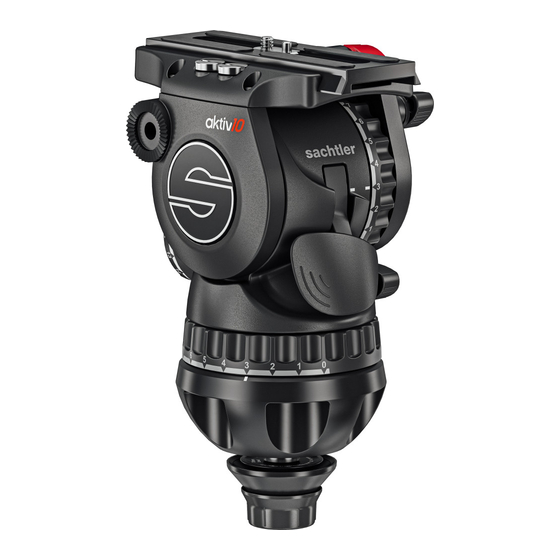
- Page 1 User Guide aktiv10, aktiv10T Fluid Head S2072S aktiv10 S2072T aktiv10T www.sachtler.com...
- Page 2 Copyright © 2021 All rights reserved. Original Instructions: English All rights reserved throughout the world. No part of this publication may be stored in a retrieval system, transmitted, copied or reproduced in any way, including, but not limited to, photocopy, photograph, magnetic or other record without the prior agreement and permission in writing of the Vitec Group Plc.
-
Page 3: Table Of Contents
Contents Safety . . . . . . . . . . . . . . . . . . . . . . . . . . . . . . . . . . . . 2 Mounting Dismounting Camera (T&G) . -
Page 4: Safety
Safety Health and Safety Important information on the safe installation and operation of this product . Read this information before operating the product . WARNING! Risk of personal injury or injury to others. All For your personal safety, read these instructions . personnel must be fully trained and adhere to correct manual handling techniques and Health &... -
Page 5: Maintenance
Safety Maintenance WARNING! The fitting of non-approved parts and or accessories or servicing by non-approved personnel could effect the safety of the product. It may also invalidate the terms and conditions of the product warranty. CAUTION! When replacing the battery, only use the same or an equivalent type of battery recommended for use with this product. -
Page 6: About This Guide
Intended Use Serial Number Location Located under the camera plate on both Touch and Go and Sideload The Sachtler aktiv fluid head has been developed to enable smooth cradles. pan and tilt movement giving the operator total image control through a wide range of angles. -
Page 7: Box Contents
Box Contents Item Description Part No aktiv10 fluid head (Sideload) S2072S aktiv10T fluid head (touch & Go) S2072T aktiv100 bowl connector S2080-0013 Touch & Go camera plate S 0364 Sideload camera plate S 0164 Pan bar plus right 0992SP User guide... -
Page 8: Optional Speedswap Accessories
Optional SpeedSwap Accessories S2080-0013 S2080-0006 aktiv bowl connector 100 mm S2080-0004 Adaptor aktiv slider / tripod 100 mm Adaptor aktiv head / slider 100 mm... -
Page 10: Operating Elements
Operating Elements Left View Rosette for left pan bar Sideload System Vertical brake Horizontal brake Horizontal drag control SpeedLevel Lever Vertical drag control Sideload plate lock Spare camera screws Illumination for drag and counterbalance Levelling bubble PrismBubble plus on / off switch Sideload system safety lock Touch &... -
Page 11: Right View
Operating Elements Right View Sideload camera plate Touch & Go camera plate Rosette for right pan bar Sideload system Bowl Counterbalance control Balance plate clamp knob Touch & Go system safety lock Touch & Go System... -
Page 12: Prismbubble
Operating Elements PrismBubble The fluid head is fitted with an illuminating bubble level which allows easy levelling in poor lighting conditions. The head also features a prism to view the bubble when the head is too high to view from above. This Prism also incorporates the On / Off switch. -
Page 13: 1St Time Installation
Scan the QR Code to see installation video or type 3. Align the flats on the thread of the Connector Stud with the flat on into browser: sachtler .com/aktiv-head-installation the Adjustment Knob. See diagram below for the visual flat markers on the Adjustment Knob and Connector Stud. -
Page 14: Mounting Head And Setting Connector Tension
1st Time Installation Mounting the Head and Setting Connector Lower the head onto the Bowl Connector and release the Tension SpeedLevel Lever. Apply the horizontal and vertical brakes and hold the head firmly with one hand. Lift the SpeedLevel Lever as shown all the way to the top. CAUTION! Try to lift the head from the tripod to ensure it has latched onto the connector. - Page 15 1st Time Installation To set the connector tension, raise the tripod so the head is at The tension is correct when the SpeedLevel Lever is released eye level. and sits between approximately 60° and 45° (30 mm to 50 mm (1”...
-
Page 16: Operation
Operation Attaching, Levelling and Dismounting the Lower the head onto the Bowl Connector and release the SpeedLevel lever. Fluid Head From the Tripod CAUTION! Push the SpeedLevel Lever fully closed against the head body before use . Attach Head to Tripod Apply the horizontal and vertical brakes and hold the head firmly WARNING! with one hand. - Page 17 Operation Levelling the Fluid Head View the bubble from above, or through the horizontal prism window (in poor light conditions operate the illumination for a To level the head lift the SpeedLevel lever until the head is loose better view). to enable levelling.
-
Page 18: Mounting Dismounting Camera (T&G)
Operation Mounting and Dismounting the Camera (Touch and Go) Apply the horizontal and vertical brakes. With the safety button held down, move the locking lever as far as possible to the left. Hold the camera plate or camera with one hand. Grasp the locking The camera plate or camera will be released from the lever with your thumb and index finger and pull down the safety sliding balance plate. - Page 19 Operation Attach the camera plate to the camera around its centre of gravity. . Mount the camera plate and camera onto the sliding balance plate. It will lock automatically and the lock lever will click audibly back into its initial position.
-
Page 20: Mounting Dismounting The Camera (Sideload)
Operation Mounting and Dismounting the Camera (Sideload) Apply the horizontal and vertical brakes. Push the safety lock (1) and release the plate (2). Attach the camera plate to the camera around its centre of gravity, Release the clamp knob. observe the arrow on the plate indicating the direction of the arrow. Additional screws are stored in the sliding balance plate assembly. - Page 21 Operation Place the camera plate into the dovetail and lower into place. It will lock automatically and the lock lever will click audibly back into its initial position. Firmly lock the plate in position after the balance procedure using the clamp knob.
-
Page 22: Fitting The Pan Bar
Operation Fitting the Pan Bar Adjusting the Pan Bar Fit and adjust the pan bar to the desired position, tighten the clamping To adjust the position of the pan bar, loosen the clamping screw screw ensuring the teeth mesh fully. sufficiently to allow the rosettes to rotate without fowling. -
Page 23: Configuring The Pan Bar
Operation Configuring the Pan Bar As standard, the pan bar is configured to mount on the right hand side of the fluid head. The pan bar can be configured for left hand mounting, as follows:... -
Page 24: Balancing The Payload
Operation Balancing the Payload Apply the vertical brake and adjust the vertical setting of the fluid drag to “0”. Set the counterbalance adjustment knob to “0”. Before operating the fluid head, the payload (camera, lens and any other fitted accessories) must be correctly balanced to ensure safe and reliable operation. - Page 25 Operation If the payload tilts backwards (points up), slide it towards the Counterbalance Adjustment front of the fluid head. Re-lock the sliding balance plate. If the platform stops in a horizontal position (camera pointing directly forward) or falls away evenly in either direction, the balance is correct.
-
Page 26: Additional C Of G Adjustments
Operation Adjusting the Counterbalance Additional C of G Adjustments The fluid head is equipped with a 15 + 0 step counterbalance adjuster If it is not possible to correctly set the payload C of G using the to accurately balance the payload. standard method: Move the camera plate to offset the payload further in the required Moving the counterbalance from one setting to another... - Page 27 Operation If the payload continues to move upwards when released, the Tilt the payload through positive and negative angles of travel, balance is set too high. Lower the balance adjuster setting by one checking that the payload remains at any angle of tilt unsupported. increment and retest.
-
Page 28: Adjusting The Drags
Operation Adjusting the Drags The fluid head is equipped with horizontal and vertical drag controls. The drags help to eliminate jerks and vibrations when moving the fluid head during filming. The drags can also be fully disengaged. CAUTION! Always set the drag adjusters to the index positions. -
Page 29: Transportation Head Settings
Operation Transportation Head Settings Transporting with the Pan Bar To ensure smooth and reliable operation over the long life of the fluid To transport the fluid head with the pan bar attached, stow in the head, the following settings should be applied to the controls during vertical position with the tripod legs to prevent damage. -
Page 30: Maintenance
Maintenance Cleaning and Inspection Clean the fluid head regularly using a soft cloth. For heavier dirt use a soft brush and a mild detergent. Regular inspections are not required. Changing the Battery The illuminated bubble level is powered by one standard type button cell (CR2032, 3 V). -
Page 31: Bowl Connector Trouble Shooting
Bowl Connector Trouble Shooting In the unlikely event that the upper cup and spring become disconnected from the Stud . Slide the upper cup and spring back onto the stud shaft and hook the spring tang into the bronze cone locating hole from the inside. Spring Locating Hole Spring Tang Gently push and twist the cup until the spring latches into the lip on... -
Page 32: Technical Specification
Technical Specification Weight Tilt range aktiv10 2.9 kg (6.4 lb) aktiv10 +90° to -70° aktiv10T 3.0 kg (6.6 lb) aktiv10T +90° to -70° Max . Payload Camera fitting aktiv10 12 kg (26.5 lb) Touch & Go camera plate S (# 0364) aktiv10T 12 kg (26.5 lb) -
Page 33: General Notices
General Notices UK Declaration of Conformity the following measures: • Reorient or relocate the receiving antenna. Vitec Production Solutions Ltd. declares under our sole • Increase the separation between the equipment and receiver. responsibility that the product detailed in this manual conforms with •... - Page 36 Publication No. S2072-4980/1 www.sachtler.com...
Need help?
Do you have a question about the aktiv10 and is the answer not in the manual?
Questions and answers