Table of Contents
Advertisement
Quick Links
Advertisement
Table of Contents

Related Manuals for Sachtler FSB 14T MK ll


Summary of Contents for Sachtler FSB 14T MK ll
- Page 1 User Guide Fluid Head Part No. S2077-0002 www.sachtler.com...
- Page 2 Copyright © 2021 All rights reserved. Original Instructions: English All rights reserved throughout the world. No part of this publication may be stored in a retrieval system, transmitted, copied or reproduced in any way, including, but not limited to, photocopy, photograph, magnetic or other record without the prior agreement and permission in writing of the Vitec Group Plc.
-
Page 3: Table Of Contents
Contents Safety........2 Mounting to a Tripod..... 8 Converting the Head Into a Flat Base . -
Page 4: Safety
Safety Health and Safety Important information on the safe installation and operation of this product. Read this information before operating the product. For your personal safety, read these instructions. WARNING! Risk of personal injury or injury to others. All personnel must be fully trained and adhere to correct manual Do not operate the product if you do not understand how to use handling techniques and Health &... -
Page 5: Maintenance
Safety Maintenance WARNING! The fitting of non-approved parts and or accessories or servicing by non-approved personnel could effect the safety of the product. It may also invalidate the terms and conditions of the product warranty. CAUTION! When replacing the battery, only use the same or an equivalent type of battery recommended for use with this product. -
Page 6: About This Guide
About this Guide Intended Use Warranty The Sachtler FSB ll fluid head range has been developed to enable This product is covered by a one year warranty. smooth pan and tilt movement giving the operator total image control The warranty will be invalidated if: through a wide range of angles. -
Page 7: Box Contents
Box Contents Item Description Part No FSB 14T ll fluid head (Touch & Go) S2077-0002 S2052-1100 Tie down 100mm Touch & Go Camera plate 16 1064 Pan bar 3470 S2077-4980 User guide... -
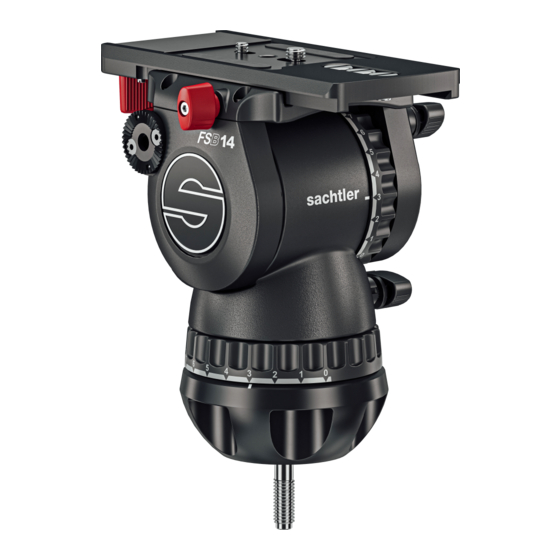
Page 8: Operating Elements
Operating Elements Left View Vertical brake Touch & Go system lock lever Touch & Go System Touch & Go system safety lock Counterbalance adjustment knob Illuminated touch bubble Horizontal brake Vertical drag control Rosette for left pan bar... -
Page 9: Operating Elements
Operating Elements Right View Touch & Go camera plate Spare camera screws Horizontal drag control Tie down mounting Balance platform clamp knob Rosette for right pan bar... -
Page 10: Installation
Mounting the Fluid Head The fluid head is fitted with an illuminating bubble level which allows The fluid head is designed to be installed onto Sachtler 100 mm tripod easy levelling in poor lighting conditions. It also illuminates the drag using the tie down. -
Page 11: Converting The Head Into A Flat Base
Installation Move the head so that the level bubble is central. Tighten the tie Converting the Head Into a Flat Base down, release the horizontal brake and check the level bubble Unscrew the centre tie down stud (retain for future use) to make a remains central. -
Page 12: Mounting Dismounting Camera
Installation Mounting and Dismounting the Camera With the safety button held down, move the locking lever as far as possible to the left. Apply the horizontal and vertical brakes. The camera plate or camera will be released from the sliding balance plate. Hold the camera plate or camera with one hand. - Page 13 Installation Attach the camera plate to the camera around its centre of gravity. Mount the camera plate and camera onto the sliding balance plate. Additional screws are stored in the sliding balance plate assembly. It will lock automatically and the lock lever will click audibly back into its initial position.
-
Page 14: Fitting The Pan Bar
Installation Fitting the Pan Bar Adjusting the Pan Bar Fit and adjust the pan bar to the desired position, tighten the clamping To adjust the position of the pan bar, loosen the clamping screw sufficiently to allow the rosettes to rotate without fowling. screw ensuring the rosette teeth mesh fully. -
Page 15: Configuring The Pan Bar
Installation Configuring the Pan Bar As standard, the pan bar is configured to mount on the right hand The pan bar may be extended, as follows: side of the fluid head. The pan bar can be configured for left hand mounting, as follows:... -
Page 16: Balancing The Payload
Installation Apply the vertical brake and adjust the vertical setting of the fluid Balancing the Payload drag to “0”. Set the counterbalance adjustment knob proportionate to the to the payload fitted. Before operating the fluid head, the payload (camera, lens and any other fitted accessories) must be correctly balanced to ensure safe and reliable operation. - Page 17 Installation If the payload tilts backwards (points up), slide it towards the Counterbalance Adjustment front of the fluid head. Re-lock the sliding balance plate. If the platform stops in a horizontal position (camera pointing directly forward) or falls away evenly in either direction, the balance is correct.
-
Page 18: Additional C Of G Adjustments
Installation Adjusting the Counterbalance Additional C of G Adjustments The fluid head is equipped with a 15 step counterbalance adjuster to If it is not possible to correctly set the payload C of G using the standard method: accurately balance the payload. Move the camera plate to offset the payload further in the required Note, moving the counterbalance from one setting to another requires the head to pass the horizontal position to take affect. - Page 19 Installation If the payload continues to move upwards when released, the Tilt the payload through positive and negative angles of travel, balance is set too high. Lower the counterbalance adjuster setting checking that the payload remains at any angle of tilt unsupported. by one increment and retest.
-
Page 20: Adjusting The Drags
Installation Adjusting the Drags The fluid head is equipped with horizontal and vertical seven step drag controls. The drags help to eliminate jerks and vibrations when moving the fluid head during filming. The drags can also be fully disengaged. CAUTION! Always set the drag adjusters to the index positions. -
Page 21: Transportation
Transportation Transportation Head Settings Transporting with the Pan Bar To ensure smooth and reliable operation over the long life of the fluid To transport the fluid head with the pan bar attached, stow in the head, the following settings should be applied to the controls during vertical position with the tripod legs to prevent damage. -
Page 22: Maintenance
Maintenance Cleaning and Inspection Clean the fluid head regularly using a soft cloth. For heavier dirt use a soft brush and a mild detergent. Regular inspections are not required. Changing the Battery The illuminated bubble level is powered by one standard type button cell (CR2032, 3 V). -
Page 23: Technical Specification
Technical Specification Weight Temperature range 3.2 kg (7.1 lb) -40°C (-40°F) to +60°C (+140°F) FSB 14T ll Camera fitting Max. Payload Touch & Go camera plate 16 (#1064) 16 kg (35.3 lb) FSB 14T ll Pan bar type Pan bar DV right (telescopic) Height FSB 14T ll 186 mm (7.3 in) Diameter 18/22/32 mm 0.7/0.9/1.3 in... -
Page 24: General Notices
General Notices UK Declaration of Conformity Vitec Production Solutions Ltd. declares under our sole responsibility that the product detailed in this manual conforms with all relevant provisions of the following UK Regulations: The Electromagnetic Compatibility Regulations 2016 The Restriction of the Use of Certain Hazardous Substances in Electrical and Electronic Equipment Regulations 2012 A copy of the declaration is available on request. - Page 25 General Notices Environmental considerations European Union Waste of Electrical and Electronic Equipment (WEEE) Directive (2012/19/EU) This symbol marked on the product or its packaging indicates that this product must not be disposed of with general household waste. In some countries or European Community regions separate collection systems have been set up to handle the recycling of electrical and electronic waste products.
- Page 28 Publication No. S2077 - 4980/0 www.sachtler.com...
Need help?
Do you have a question about the FSB 14T MK ll and is the answer not in the manual?
Questions and answers