Table of Contents
Advertisement
Quick Links
Advertisement
Table of Contents

Related Manuals for Sachtler Vario Ped 2-80


Summary of Contents for Sachtler Vario Ped 2-80
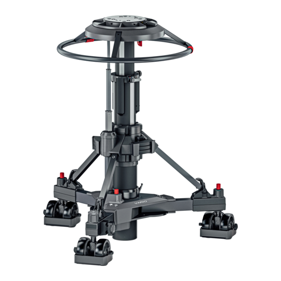
- Page 1 User Guide VARIO PED 2-80 Pedestal Part No. S2303-0001 www.sachtler.com...
- Page 2 Copyright © 2022 All rights reserved. Original Instructions: English All rights reserved throughout the world. No part of this publication may be stored in a retrieval system, transmitted, copied or reproduced in any way, including, but not limited to, photocopy, photograph, magnetic or other record without the prior agreement and permission in writing of the Videndum Group Plc.
-
Page 3: Table Of Contents
Contents Safety..........2 Operation. -
Page 4: Safety
Under no circumstances should the product be used for The Vario Ped 2-80 is designed for use in television studios and OB the transportation or support of personnel. application to support and balance fluid heads, cameras and ancillary equipment weighing up to 80 kg (176 lb). -
Page 5: Water, Moisture And Dust
Safety Maintenance WARNING! The product must only be operated on a smooth and level surface. WARNING! The fitting of non-approved parts or accessories, or the carrying out of non-approved WARNING! The product must always be secured (all alterations or servicing can be dangerous and could three wheel brakes applied) when left unattended. -
Page 6: Usage
It has a selector for both single wheel and all wheel crab steering for working in tight spaces and on shot direction The Vario Ped 2-80 pedestal is designed for use in television studios changes. It comes with 12.5cm / 5 inch wheels and adjustable cable and on location to support and balance a fluid head, camera and guards. -
Page 7: Components And Connections
Components and Connections Box Contents Item Description Vario Ped 2-80 S2303-0001 Trim weights x 6 Skid + Studio wheels Manual Pump... - Page 8 Components and Connections Item Description Four-bolt mounting plate Pressure gauge Weight tray Steering indicator Moving column Safety catch Trim weight Fixed strut Skid clamp Foot support and strap Wheel brake foot-button Cable guard...
- Page 9 Components and Connections Item Description Outer Tube Crab/steer changeover foot-button Cable clamp Tiller socket Adjustable strut Trim weight stowage Drag control On-shot clamp Removable steering ring Steering ring mounting plate Schrader valve and cap...
-
Page 10: Optional Accessories
Components and Connections Optional Accessories Item Description Part No. 150mm Bowl Adaptor 3330-17 Quickfix kit 3912 Pedestal Accessory Holder V4172-1003 OB Wheels 3329-30 Kick ring 3329-32 Steering ring small 3374-17 Tracking Dolly / Skid 3369-57 100mm Bowl Adaptor 3330-16 Base Adaptor 8349 PTZ and Prompter plate V4166-1002... -
Page 11: Assembling The Pedestal
Installation Assembling the Pedestal Turn the skid upside-down, depress the leg locking plungers and swing each folding leg out until the plungers lock the legs in the fully open position. Set the skid on the ground on its wheels and apply the brakes (3). Ensure that the rubber straps on each foot support (2) are to the outside of the ball joint. -
Page 12: Column
Installation Column Install the column on the skid as follows: Ensure that the rubber straps on each foot support (10) are to the outside of the ball joint. Hold the column upright. Raise the struts (8 and 18) to about 30° from horizontal. - Page 13 Installation Tighten the skid clamp (9), using moderate hand pressure only. The clamp lever has a spring-loaded ratchet-type action and is operated as follows: Turn the clamp lever clock-wise as far as possible. Pull the lever outward against the spring pressure, return it to vertical and release.
- Page 14 Apply downward pressure to the top plate, unlatch the safety catch. The pedestal has the standard four-bolt mounting plate which permits the use of various Sachtler fluid heads or optional accessories with Using hand guidance, allow the column to rise to its maximum four-bolt fixing (See Optional Accessories page 8).
- Page 15 CAUTION! It is recommend a second person hold the Lower and re-latch the column before adding all items such as pan payload steady while another person tightens the screw bars, prompters, lenses etc. Attaching these items at a later stage bolts.
-
Page 16: Heavy Duty Quickfix Alternative Mounting Accessory
BUTTON LATCH Install Quickfix adaptor (Installation is explained in the previous section_Page 12.) Attach the Multi Disk to the Sachtler Studio fluid head UNLOCKED LOCKED (except Video 90) Push up the red safety latch and unlock the adaptor by pulling the lever fully outwards and to the left. -
Page 17: Pressurizing The Pedestal
The pedestal is The pedestal may be pressurized by using the Sachtler Portable fitted with a pressure relief valve as a safeguard against Pump or from an external pressure source. -
Page 18: Pressurizing The Pedestal Using The Portable Pump
Installation Pressurizing the pedestal using the Disconnect the pump hose and valve adaptor from the pedestal charging valve. portable pump WARNING! Do not pressurize the pedestal beyond the maximum safe working pressure indicated by the leading edge of the red sector on the gauge. The pedestal is fitted with a pressure relief valve as a safeguard against over-pressurization. -
Page 19: Pressurizing From An External Pressure Source
Installation Pressurizing from an external pressure source WARNING! This pedestal must be pressurized only with clean, dry air or nitrogen. A pressure reducing valve must be fitted to the pressure line between the gas cylinder and the outlet connection of the hose. The reducing valve must be screwed into the gas cylinder outlet. -
Page 20: Balancing The Payload
Installation Balancing the Payload After pressurization of the pedestal, the fluid head and payload can be accurately balanced, as follows: Push down on the steering ring (22) against residual pressure and release the safety catch (6). Allow the column to extend under hand restraint. - Page 21 Installation WARNING! Do not reduce pedestal pressure below 3.5 bar (50 psi). This ensures that the elevating mechanism remains in tension. WARNING! The Schrader valve cap (3) forms a primary pressure seal. Always replace the cap and screw it down finger-tight.
-
Page 22: Operation
Operation Height adjustment Drag control The column has an on-shot stroke of 770 mm (30.3 in) and the load Column movement is adjustable for drag and this is set according to can be moved over this distance, in perfect balance, by raising and operator preference by means of the drag control (20) located at the lowering the steering ring (22). -
Page 23: Brakes
Operation Brakes Cable guards The skid is fitted with brakes on the wheels on the folding legs. The The cable guards (17) are height-adjustable and should be set as brakes are operated by pressing on the foot-buttons (4) located above required. -
Page 24: Steering
Operation Steering Pushing the foot-button (16) operates a changeover mechanism which toggles the pedestal between crab and steer. The button can be pressed with the wheels in any position, but the changeover will Directional control of the pedestal is achieved by turning the steering not occur until the wheels are all facing forward, so the steering ring mounted at the top of the column. - Page 25 Operation...
-
Page 26: Changing The Skid Tracking Width
Operation Changing the skid tracking width WARNING! To ensure maximum stability when the skid is set to narrow track, particularly when moving over The movable skid legs can be set to either of two positions. uneven ground, reduce pedestal height to a minimum 1: Wide for normal use, maximum stability. -
Page 27: Optional Wheels
Operation Optional wheels To replace the wheels: Remove the column from the skid (see Transportation and storage A set of 160 mm (6.3 in.) wheels (Part No. 3329-30) is available to on page 26 and turn the skid upside down. convert the skid from studio to OB use. -
Page 28: Transportation And Storage
Operation WARNING! Local, national or international regulations may apply to the transport and storage of pressurized pedestals, specifically, not to be classed as dangerous goods under IATA regulation UN 1956 - Compressed Gas Shipping. Pressure must be reduced to 2bar (28psi) or less. -
Page 29: Maintenance
Maintenance Release the skid clamp (9). Release the three rubber foot straps (10) from the struts. Raise the struts (8 / 18) then lift the complete column vertically off the skid. Remove the steering ring by unscrewing each fastener until it releases. Lift the steering ring off its mounting plate. Turn the skid over, depress the locking plungers and fold the skid legs, ensuring that the plungers lock in the closed position. -
Page 30: Servicing
Maintenance Servicing Routine Checks General The Vario requires minimal routine maintenance, apart from checking the connections and overall operation periodically. The Vario pedestal is robustly made to high engineering standards Check the following points during normal use: and little attention is required to maintain serviceability except for regular cleaning. -
Page 31: Skid Clamp Adjustment
Maintenance Skid clamp adjustment Elimination of radial and side play on the elevation tube or top stage The skid clamp is applied and released by turning the handle If excessive radial or side play is apparent on the elevation tube or top clockwise or counter-clockwise. -
Page 32: Technical Specification
Technical Specification Physical Data (Studio V4171-0001) Minimum height Tracking Width 660 mm (26. in.) 970 mm (38.2 in.) Maximum height Doorway Tracking Width 1430 mm (56 in.) 730 mm (28.7 in.) Stages Maximum payload 80 kg (176 lb) Weight Max working pressure 44.4 kg / 97.9 lb ≤... - Page 33 Environmental Data Operating temperature range +5°C to +40°C (41°F to +104°F) Storage temperature range -20°C to +60°C (-4°F to +140°F) Technical specifications are subject to change without notice.
-
Page 34: General Notices
General Notices General Notices EU Declaration of Conformity Videndum Production Solutions Ltd. declares under our sole responsibility, supported by Videndum Production Solutions GmbH - our authorized representative, that the product detailed in this manual conforms with all relevant provisions of the following EU directives: Machinery Directive 2006/42/EC A copy of the declaration is available on request. - Page 35 General Notices General Notices Environmental considerations European Union Waste of Electrical and Electronic Equipment (WEEE) Directive (2002/96/EC) This symbol marked on the product or its packaging indicates that this product must not be disposed of with general household waste. In some countries or European Community regions separate collection systems have been set up to handle the recycling of electrical and electronic waste products.
- Page 36 Publication No. S2303-4980/0 www.sachtler.com...
Need help?
Do you have a question about the Vario Ped 2-80 and is the answer not in the manual?
Questions and answers