Table of Contents
Advertisement
Quick Links
MODEL 33075, 33075T
VARIABLE SPEED
BENCHTOP MILL
Instruction Manual
NEED HELP? CONTACT US!
Have product questions? Need technical support? Please feel free to contact us:
1-800-232-1195 (M-F 8AM-5PM CST)
TECHSUPPORT@WENPRODUCTS.COM
IMPORTANT: Your new tool has been engineered and manufactured to WEN's highest standards for dependability,
ease of operation, and operator safety. When properly cared for, this product will supply you years of rugged,
trouble-free performance. Pay close attention to the rules for safe operation, warnings, and cautions. If you use
your tool properly and for its intended purpose, you will enjoy years of safe, reliable service.
WENPRODUCTS.COM
For replacement parts and the most up-to-date instruction manuals, visit
Advertisement
Table of Contents

Related Manuals for Wen 33075T


Summary of Contents for Wen 33075T
- Page 1 1-800-232-1195 (M-F 8AM-5PM CST) TECHSUPPORT@WENPRODUCTS.COM IMPORTANT: Your new tool has been engineered and manufactured to WEN’s highest standards for dependability, ease of operation, and operator safety. When properly cared for, this product will supply you years of rugged, trouble-free performance. Pay close attention to the rules for safe operation, warnings, and cautions. If you use your tool properly and for its intended purpose, you will enjoy years of safe, reliable service.
-
Page 2: Table Of Contents
CONTENTS WELCOME Introduction ..................... 3 Specifications ....................3 SAFETY General Safety Rules ..................4 Specific Rules for the Milling Machine ............. 6 Electrical Information ..................7 BEFORE OPERATING Unpacking & Packing List .................8 Know Your Milling Machine ................9 Assembly & Adjustment ................. 11 OPERATION &... -
Page 3: Welcome
INTRODUCTION Thanks for purchasing the WEN Benchtop Mill. We know you are excited to put your tool to work, but first, please take a moment to read through the manual. Safe operation of this tool requires that you read and understand this operator’s manual and all the labels affixed to the tool. -
Page 4: Safety
GENERAL SAFETY RULES WARNING! Read all safety warnings and all instructions. Failure to follow the warnings and instructions may result in electric shock, fire and/or serious injury. Safety is a combination of common sense, staying alert and knowing how your item works. The term “power tool” in the warnings refers to your mains-operated (corded) power tool or battery-operated (cordless) power tool. - Page 5 GENERAL SAFETY RULES WARNING! Read all safety warnings and all instructions. Failure to follow the warnings and instructions may result in electric shock, fire and/or serious injury. Safety is a combination of common sense, staying alert and knowing how your item works. The term “power tool” in the warnings refers to your mains-operated (corded) power tool or battery-operated (cordless) power tool.
-
Page 6: Specific Rules For The Milling Machine
SPECIFIC RULES FOR THE MILLING MACHINE WARNING! Do not operate the power tool until you have read and understood the following instructions and the warning labels. MILL MACHINE SAFETY 8. Use the appropriate speed for the task and workpiece. The harder the workpiece and the larger the cutter diam- 1. -
Page 7: Electrical Information
ELECTRICAL INFORMATION GROUNDING INSTRUCTIONS In the event of a malfunction or breakdown, grounding provides the path of least resistance for an electric current and reduces the risk of electric shock. This tool is equipped with an electric cord that has an equipment grounding conductor and a grounding plug. -
Page 8: Before Operating
UNPACKING & PACKING LIST UNPACKING With the help of a friend or trustworthy foe, such as one of your in-laws, carefully remove the milling machine from the packaging and place it on a sturdy, flat surface. Make sure to take out all contents and accessories. Do not dis- card the packaging until everything is removed. -
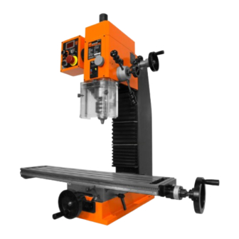
Page 9: Know Your Milling Machine
KNOW YOUR MILLING MACHINE TOOL PURPOSE Remove material from your workpiece with your WEN Benchtop Mill. Refer to the following diagrams to become familiarized with all the parts and controls of your milling machine. The components will be referred to later in the manual for assembly and operation instructions. - Page 10 KNOW YOUR MILLING MACHINE TOOL PURPOSE Remove material from your workpiece with your WEN Benchtop Mill. Refer to the following diagrams to become familiarized with all the parts and controls of your milling machine. The components will be referred to later in the manual for assembly and operation instructions.
-
Page 11: Assembly & Adjustment
A vise (not included) is a crucial attachment to hold your workpiece in place when using the milling machine. You can purchase a milling vise or quick vise that is suitable for your workpiece and milling operation. The WEN 33124A 3.5 inch Quick Release Vise is perfect for holding your workpieces. - Page 12 They are also less expensive than end mill holders. The WEN 33182A 8-Piece Imperial Steel Collet Set is a great set to hold you over. • End Mill Holders (not included) End mill holders are longer than collets and so the cutter can reach closer to the machine’s worktable.
- Page 13 ASSEMBLY & ADJUSTMENTS REMOVING THE DRILL CHUCK Fig. 4 The drill chuck and taper shank are pre-installed on your milling ma- chine. To replace the drill chuck with a collet or end mill holder, follow the steps below for removing the drill chuck. Cover the table with a spare towel or rag to protect it from getting damaged, in case parts or bits are dropped onto the table.
- Page 14 ASSEMBLY & ADJUSTMENTS ADJUSTING THE TABLE TRAVEL Fig. 6 The milling machine’s worktable can be adjusted along the X axis and Y axis to accurately control the cutting location. The gauge on each handwheel indicates the distance of travel. 1. To move the table along the longitudinal (X) axis (left and right), loosen the longitudinal feed lock lever (Fig.
- Page 15 ASSEMBLY & ADJUSTMENTS ADJUSTING THE HEADSTOCK HEIGHT Fig. 9 The headstock on your mill can be adjusted up and down to accom- modate short or tall workpieces and enables you to change tools mid project. The dovetail design creates precise Z-axis movement that allows you to keep your workpiece aligned when changing the head- stock height or changing tooling.
-
Page 16: Operation & Maintenance
ASSEMBLY & ADJUSTMENTS TURNING ON / OFF AND ADJUSTING THE SPEED Fig. 12 The speed adjustment knob on the front of the control panel (Fig. 12 - 1) turns the machine ON and OFF and adjusts the speed within the unit’s capable speed range. - Page 17 OPERATION PRIOR TO OPERATION Check that the following requirements are met before plugging in the machine: • The anti-rust protection has been cleared off from the machine. • All obstacles have been cleaned and removed from the machine area and worktable. •...
-
Page 18: Maintenance
MAINTENANCE WARNING! To avoid accidents, make sure the power switch is in the OFF position and unplug the tool from the electrical outlet before cleaning or performing any maintenance. Servicing of the tool must be performed by a qualified technician. GENERAL MAINTENANCE 1. - Page 19 MAINTENANCE WARNING! To avoid accidents, make sure the power switch is in the OFF position and unplug the tool from the electrical outlet before cleaning or performing any maintenance. Servicing of the tool must be performed by a qualified technician. GIBS ADJUSTMENT The gib act as a sliding interface between two slide faces.
-
Page 20: Troubleshooting Guide
TROUBLESHOOTING GUIDE WARNING! Stop using the generator immediately if any of the following problems occur or risk serious personal injury. If you have any questions, please contact customer service at 1-800-232-1195 (M-F 8-5 CST), or email techsupport@wenproducts.com. 1. Emergency stop button is 1. - Page 21 TROUBLESHOOTING GUIDE WARNING! Stop using the generator immediately if any of the following problems occur or risk serious personal injury. If you have any questions, please contact customer service at 1-800-232-1195 (M-F 8-5 CST), or email techsupport@wenproducts.com. 1. Spacing between the sensor ad the timing gear is 1.
-
Page 22: Exploded View & Parts List
EXPLODED VIEW & PARTS LIST 58 6 23 5 96 95 69 20... - Page 23 EXPLODED VIEW & PARTS LIST PART NO. DESCRIPTION QTY. PART NO. DESCRIPTION QTY. .2-1 33075-201 Spindle box .2-33 33075-233 Spanner nut .2-2 33075-202 R8 spindle sleeve .2-34 33075-234 Upper Spindle Washer 1 .2-3 33075-203 R8 spindle .2-37 33075-237 Set Screw M6x10 .2-4 33075-204 Base plate...
- Page 24 EXPLODED VIEW & PARTS LIST PART NO. DESCRIPTION QTY. PART NO. DESCRIPTION QTY. .2-71 33075-271 Cap screw M10x16 .2-86 33075-286 Handle sleeve .2-72 33075-272 Sleeve limit washer .2-87 33075-287 Locking rod Right shaft gear support .2-88 33075-288 Hex head screw M4x40 .2-73 33075-273 flange...
- Page 25 EXPLODED VIEW & PARTS LIST...
- Page 26 EXPLODED VIEW & PARTS LIST PART NO. DESCRIPTION QTY. PART NO. DESCRIPTION QTY. .3-1 33075-301 Column .3-18 33075-318 M8 lock nut .3-2 33075-302 Leadscrew .3-19 33075-319 Key 4x16 .3-3 33075-303 Leadscrew locking nut .3-20 33075-320 Lifting shaft .3-4 33075-304 Leadscrew lift nut .3-21 33075-321 Pin 3x16...
- Page 27 EXPLODED VIEW & PARTS LIST...
- Page 28 EXPLODED VIEW & PARTS LIST PART NO. DESCRIPTION QTY. PART NO. DESCRIPTION QTY. .4-1 33075-401 Left bracket cover Slotted screw M8- .4-21 33075-317 1.25x55 Left leadscrew sleeve .4-2 33075-402 seat Handwheel curved .4-22 33075-313 spring Left longitudinal lead- .4-3 33075-403 screw sleeve .4-23 33075-423 Thrust ball bearing 8101...
- Page 29 EXPLODED VIEW & PARTS LIST...
- Page 30 EXPLODED VIEW & PARTS LIST PART NO. DESCRIPTION QTY. PART NO. DESCRIPTION QTY. .5-1 33075-501 Lower splash guard .5-14 33075-514 Washer 5 .5-2 33075-502 Upper splash guard .5-15 33075-515 Outer shield .5-3 33075-503 Front plate cover .5-16 33075-208 Cap screw M4x10 .5-4 33075-257 Cross head screw M5x6 .5-17...
- Page 31 EXPLODED VIEW & PARTS LIST...
- Page 32 EXPLODED VIEW & PARTS LIST PART NO. DESCRIPTION QTY. PART NO. DESCRIPTION QTY. .6-1 33075-601 Tapping screw M3x9 .6-17 33075-617 Power socket .6-2 33075-602 FWD/REV switch .6-18 33075-618 M3 nut .6-3 33075-603 Emergency stop button .6-19 33075-619 Back cover .6-4 33075-604 Fault light Cross head pan screw...
-
Page 33: Warranty Statement
WARRANTY STATEMENT WEN Products is committed to building tools that are dependable for years. Our warranties are consistent with this commitment and our dedication to quality. LIMITED WARRANTY OF WEN PRODUCTS FOR HOME USE GREAT LAKES TECHNOLOGIES, LLC (“Seller”) warrants to the original purchaser only, that all WEN consumer power tools will be free from defects in material or workmanship during personal use for a period of two (2) years used for professional or commercial use. - Page 34 NOTES...
- Page 35 NOTES...
- Page 36 THANKS FOR REMEMBERING V. 2021.06.18...
Need help?
Do you have a question about the 33075T and is the answer not in the manual?
Questions and answers