Advertisement
Table of Contents
- 1 Table of Contents
- 2 Product Specifications
- 3 Safety Introduction
- 4 General Safety Rules
- 5 Specific Rules for the Milling Machine
- 6 Electrical Information
- 7 Know Your Milling Machine
- 8 Assembly & Preparation
- 9 Adjustments
- 10 Operation
- 11 Maintenance
- 12 Exploded View & Parts List
- Download this manual
3072101
For replacement parts visit
WENPRODUCTS.COM
Your new tool has been engineered and manufactured to WEN's highest standards for dependability, ease
of operation, and operator safety. When properly cared for, this product will supply you years of rugged,
trouble-free performance. Pay close attention to the rules for safe operation, warnings, and cautions. If
you use your tool properly and for its intended purpose, you will enjoy years of safe, reliable service.
NOTICE: Please refer to wenproducts.com for the most up-to-date instruction manual.
IMPORTANT:
NEED HELP? CONTACT US!
Have product questions? Need technical support?
Please feel free to contact us at:
800-232-1195
techsupport@wenproducts.com
WENPRODUCTS.COM
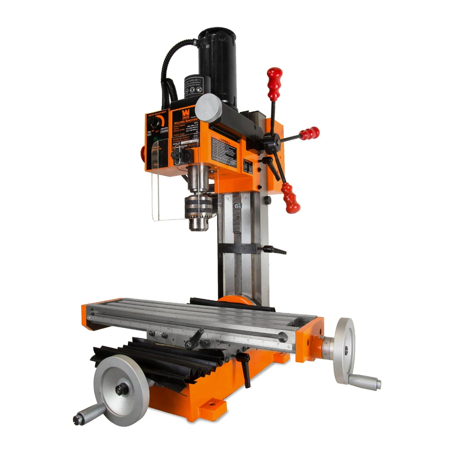
MILLING
MACHINE
(M-F 8AM-5PM CST)
Model # 33013
bit.ly/wenvideo
Advertisement
Table of Contents

Related Manuals for Wen 33013


Summary of Contents for Wen 33013
- Page 1 WENPRODUCTS.COM IMPORTANT: Your new tool has been engineered and manufactured to WEN’s highest standards for dependability, ease of operation, and operator safety. When properly cared for, this product will supply you years of rugged, trouble-free performance. Pay close attention to the rules for safe operation, warnings, and cautions. If you use your tool properly and for its intended purpose, you will enjoy years of safe, reliable service.
-
Page 2: Table Of Contents
Adjustments Operation Maintenance Exploded View & Parts List Warranty Statement PRODUCT SPECIFICATIONS Model Number: 33013 Motor: 120V, 60Hz, 4.5A Drilling Bit Diameter Capacity: 1/2 in. (13 mm) End Milling Bit Diameter Capacity: 5/8 in. (16 mm) Face Milling Bit Diameter Capacity: 1-1/8 in. -
Page 3: Safety Introduction
SAFETY INTRODUCTION Thanks for purchasing the WEN Milling Machine. This is an exciting moment. You have received your new tool, opened the box, and are now about to read through the instruction manual. This manual provides information regarding potential safety concerns, as well as helpful assembly and operating instructions. Safe operation of this tool requires that you read and understand this operator’s manual and all labels affixed to the tool. -
Page 4: General Safety Rules
GENERAL SAFETY RULES WARNING! Read all safety warnings and instructions. Failure to follow all instructions may result in electric shock, fire and serious injury. The term “power tool” in the warnings refers to your mains- operated (corded) power tool. Save all warnings and instructions for future reference. WORK AREA SAFETY 1. - Page 5 GENERAL SAFETY RULES 6. Dress properly. Do not wear loose clothing or jewelry. Keep your hair, clothing and gloves away from moving parts. Loose clothes, jewelry or long hair can be caught in moving parts. 7. If devices are provided for the connection of dust extraction and collection facilities, ensure these are connected and properly used.
-
Page 6: Specific Rules For The Milling Machine
SPECIFIC RULES FOR THE MILLING MACHINE 1. Your milling machine is designed for drilling, end milling and face milling operations on small workpieces. Us- ing the machine for any other purpose for which it is not designed may result to serious injuries and/or damage to the machine. -
Page 7: Electrical Information
ELECTRICAL INFORMATION GROUNDING INSTRUCTIONS In the event of a malfunction or breakdown, grounding provides the path of least resistance for an electric current and reduces the risk of electric shock. This tool is equipped with an electric cord that has an equipment grounding conductor and a grounding plug. -
Page 8: Know Your Milling Machine
KNOW YOUR MILLING MACHINE UNPACKING THE MACHINE Prepare a sturdy and level surface on the ground that can support the weight of the machine. Open the crate and unbolt the machine from the skid. This big boy is very heavy, so get a good friend (or a trustworthy foe) to help you lift and assemble the machine. - Page 9 KNOW YOUR MILLING MACHINE PACKING LIST Drill Chuck & Large Wrench M36 Double End Wrench x 3 Spindle Lock Rod Taper Shank (For loosening the bevel (Pre-installed, for holding lock nut) drill bits) M8/M10 M14/M17 M17/M19 Hook Spanner Wrench Hex Wrench x 4 D45-52 Handle x 2 Drill Chuck Key...
-
Page 10: Assembly & Preparation
(mounting hardware not included). TIP: Your milling machine is compatible with the 115mm 180mm WEN 6588 Multipurpose Planer Stand, available at wenproducts.com. Forget measuring and drilling 410mm holes on your workbench, simply mount your ma- chine onto the mobile stand with pre-drilled holes, Fig. - Page 11 ASSEMBLY & PREPARATION Your machine can work as both a milling and drilling machine, depending on the type of cutter that is installed. Refer to the introduction below for some common cutter holders and cutting tools that you can install onto your machine.
- Page 12 ASSEMBLY & PREPARATION WARNING: To prevent injury from accidental operation, make sure the tool is switched OFF and un- plugged from the power source before assembling the tool or making any adjustments. REMOVING THE DRILL CHUCK TAPER SHANK The drill chuck and taper shank are pre-installed on your milling machine. To replace the drill chuck with a collet or end mill holder, follow the steps below for removing the drill chuck.
-
Page 13: Adjustments
ADJUSTMENTS WARNING: To prevent injury from accidental operation, make sure the tool is switched OFF and un- plugged from the power source before assembling the tool or making any adjustments. ADJUSTING THE TABLE TRAVEL The milling machine’s worktable can be adjusted along the X axis and Y axis to accurately set the cutting location. The gauge on each handwheel indicates the distance of travel. - Page 14 ADJUSTMENTS WARNING: To prevent injury from accidental operation, make sure the tool is switched OFF and un- plugged from the power source before assembling the tool or making any adjustments. SETTING THE DEPTH STOP 1. Loosen the depth stop lock lever (Fig. 5 - 4 p. 13). 2.
-
Page 15: Operation
OPERATION WARNING: To prevent serious injury, make sure all the warnings and instructions have been read and understood before operating this tool. WARNING: Always wear ANSI Z87.1-approved eye protection and a face shield/dust mask when using this machine. Chips and dust fly at high speed during operation, and may cause injuries if they hit you. PRIOR TO OPERATION Check that the following requirements are met before plugging in the machine: •... -
Page 16: Maintenance
MAINTENANCE WARNING: To avoid accidents, make sure the power switch is in the OFF position and unplug the tool from the electrical outlet before cleaning or performing any maintenance. Servicing of the tool must be performed by a qualified technician. GENERAL MAINTENANCE 1. - Page 17 • X-axis gib (Part No. 33013-036), between saddle seat and worktable slide face. • Y-axis gib(Part No. 33013-034), between base and saddle seat slide face. • Z-axis lower gib (Part No. 33013-045), between column and bevel center slide face. • Z-axis upper gib (Part No. 33013-064), between column and headstock slide face.
-
Page 18: Exploded View & Parts List
EXPLODED VIEW & PARTS LIST Cross (X) Axis & Longitudinal (Y) Axis... - Page 19 EXPLODED VIEW & PARTS LIST Vertical (Z) Axis...
- Page 20 EXPLODED VIEW & PARTS LIST Spindle and Gear Box...
- Page 21 EXPLODED VIEW & PARTS LIST Part No. Description Part No. Description 33013-001 Base 33013-049 R8 Spindle Box 33013-002 Y-Axis Feed Screw 33013-050 Gear Shaft, 14T 33013-002-1 Key, 4 X 16 33013-051 Key, 4 X 25 33013-004 Dial 33013-052 Bevel Gear, 29T...
- Page 22 EXPLODED VIEW & PARTS LIST Part No. Description Part No. Description 33013-100 Face Shield 33013-144 Self-Tapping Screw, St2.9 X 8 33013-101 Clamping Bolt, M6 X 12 33013-145 High/Low Label 33013-102 Upper Limiting Bushing, M6 33013-146 Motor Cover 33013-103 Upper Limiting Screw, M6 x 16...
- Page 23 LIMITED TWO YEAR WARRANTY WEN Products is committed to build tools that are dependable for years. Our warranties are consistent with this commitment and our dedication to quality. LIMITED WARRANTY OF WEN CONSUMER POWER TOOLS PRODUCTS FOR HOME USE GREAT LAKES TECHNOLOGIES, LLC (“Seller”) warrants to the original purchaser only, that all WEN con- sumer power tools will be free from defects in material or workmanship for a period of two (2) years from date of purchase.
- Page 24 THANKS FOR REMEMBERING...
Need help?
Do you have a question about the 33013 and is the answer not in the manual?
Questions and answers
what is included with this mill wen 33013
The provided context does not list the specific items included with the WEN 33013 milling machine. Therefore, the answer cannot be determined from the given information.
This answer is automatically generated