Table of Contents
Advertisement
Quick Links
Advertisement
Table of Contents

Related Manuals for Pilz PSEN ma1.1p-10


Summary of Contents for Pilz PSEN ma1.1p-10
- Page 1 PSEN ma1.1p-10 PSEN sensor technology Operating Manual-22189-EN-04...
- Page 2 Preface This document is the original document. All rights to this documentation are reserved by Pilz GmbH & Co. KG. Copies may be made for the user's internal purposes. Suggestions and comments for improving this documenta- tion will be gratefully received.
-
Page 3: Table Of Contents
Requirements and connection to evaluation devices ............Installation ..........................Adjustment ..........................Periodic test ........................... Dimensions in mm ......................... Technical details ........................Safety characteristic data ......................Order reference ........................System ............................Accessories ..........................EC declaration of conformity ....................Operating Manual PSEN ma1.1p-10 22189-EN-04... -
Page 4: Introduction
PSEN ma1.1p-10 Introduction Validity of documentation This documentation is valid for the product PSEN ma1.1p-10. It is valid until new document- ation is published. This operating manual explains the function and operation, describes the installation and provides guidelines on how to connect the product. -
Page 5: Safety
In order to achieve the re- quired safety level for the overall plant/machine, define the safety requirements for the plant/machine and then define how these must be implemented from a technical and organ- isational standpoint. Operating Manual PSEN ma1.1p-10 22189-EN-04... -
Page 6: Use Of Qualified Personnel
– If spare actuators are used, these must be installed as described in Installation [ 12]. – If the original actuators are replaced with substitute actuators, the ori- ginal actuators must be destroyed before disposal. Operating Manual PSEN ma1.1p-10 22189-EN-04... -
Page 7: Unit Features
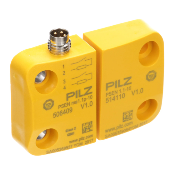
Function description If the actuator is within the response range (safety gate closed), the safety contacts of the safety switch are closed. Operate the PSEN ma1.1p-10 in conjunction with the following components: Actuator PSEN 1.1-10 (see Order reference [ 17]) and... -
Page 8: Operating Distances
Assured operating distance Min. operating distance omin Assured release distance The offset-independent values for the switching distances are included in the Technical details [ 15]. Lateral and vertical offset Legend [1] Lateral offset [2] Vertical offset Operating Manual PSEN ma1.1p-10 22189-EN-04... -
Page 9: Wiring
– On evaluation devices with AC supply voltage: Overall cable resistance ≥ 25 Ohms per channel – For details of how to perform the test for shorts across the contacts, please refer to the operating manual for the relevant evaluation device. Operating Manual PSEN ma1.1p-10 22189-EN-04... -
Page 10: Pin Assignment
Requirements and connection to evaluation devices For use of PSEN ma1.1p-10 in accordance with DIN EN 60947-5-3 an evaluation device must be connected. Connect the PSEN ma1.1p-10 either with a certified Pilz evaluation device or with an evaluation device with defined properties... - Page 11 [ of PSEN ma1.1p-10 – Always comply with the max. switching current safety contacts of PSEN ma1.1p-10. Outputs at the evaluation device must only be switched on again when both reed con- tacts at the safety switch have been opened and closed (partial operation lock)
-
Page 12: Installation
PSEN ma1.1p-10 Examples for connection to Pilz evaluation devices: PNOZ s3 PSENmag brown white blue black PNOZmulti PSENmag brown white blue black Legend Input OSSD Input OSSD T1, T2 Test pulse outputs Installation CAUTION! Potential loss of safety function due to changed device properties The unit's properties may be affected if installed in an environment contain- ing electrically or magnetically conductive material. - Page 13 (e.g. M4 cheese-head or pan head screws). Use screws made of non-magnetic material (e.g. brass). The protection type (see Technical details [ 15]) can only be achieved by using the Pilz connection leads available as an accessory. Operating Manual PSEN ma1.1p-10 | 13 22189-EN-04...
-
Page 14: Adjustment
Carry out a monthly function test on the safety switch and actuator. Always test the function with a connected evaluation device. The safety function may only be checked by qualified personnel. Dimensions in mm Operating Manual PSEN ma1.1p-10 | 14 22189-EN-04... -
Page 15: Technical Details
1 mm Shock stress In accordance with the standard EN 60947-5-2 Acceleration Duration 11 ms Airgap creepage Pollution degree Rated insulation voltage 25 V Rated impulse withstand voltage 0,33 kV Protection type Housing IP67 Operating Manual PSEN ma1.1p-10 | 15 22189-EN-04... -
Page 16: Safety Characteristic Data
You must comply with the safety characteristic data in order to achieve the required safety level for your plant/machine. B10d in accordance with EN ISO 13849-1: 2015 TM [year] in accordance with EN ISO and EN 62061 13849-1:2015 10.000.000 Operating Manual PSEN ma1.1p-10 | 16 22189-EN-04... -
Page 17: Order Reference
4-pin straight 380 201 10 m 380 202 30 m 380 203 PSS67 Cable M8af M12sm Female connector M8 380 204 angled, 4-pin 380 205 10 m 380 206 30 m 380 207 Operating Manual PSEN ma1.1p-10 | 17 22189-EN-04... -
Page 18: Ec Declaration Of Conformity
European Parliament and of the Council. The complete EC Declaration of Conformity is available on the Internet at www.pilz.com/downloads. Authorised representative: Norbert Fröhlich, Pilz GmbH & Co. KG, Felix-Wankel-Str. 2, 73760 Ostfildern, Germany Operating Manual PSEN ma1.1p-10...
Need help?
Do you have a question about the PSEN ma1.1p-10 and is the answer not in the manual?
Questions and answers