Table of Contents
Advertisement
Quick Links
Advertisement
Table of Contents

Related Manuals for Pilz PSEN op4B/1 Series


Summary of Contents for Pilz PSEN op4B/1 Series
- Page 1 PSEN op4B/1 Series PSEN sensor technology Operating Manual-1003356-EN-02...
- Page 2 Preface This document is a translation of the original document. All rights to this documentation are reserved by Pilz GmbH & Co. KG. Copies may be made for internal purposes. Suggestions and comments for improving this documentation will be gratefully received.
-
Page 3: Table Of Contents
Installation and wiring Attach safety light grid without muting sensors to mounting surface Attach safety light grid with muting sensors to mounting surface Conversion of safety light grids without muting sensors Installation of external muting sensors Operating Manual PSEN op4B/1 Series 1003356-EN-02... - Page 4 Daily check 9.1.3 Check after plant/machine modification Maintenance Section 10 Dimensions Section 11 Technical details 11.1 Safety characteristic data Section 12 Order reference 12.1 Order reference for safety light grids 12.2 Order reference for accessories Operating Manual PSEN op4B/1 Series 1003356-EN-02...
- Page 5 Content Section 13 Appendix 13.1 Check list Operating Manual PSEN op4B/1 Series 1003356-EN-02...
-
Page 6: Introduction
Introduction Introduction Validity of documentation This documentation is valid for the product PSEN op4B/1 Series. It is valid until new docu- mentation is published. This operating manual explains the function and operation, describes the installation and provides guidelines on how to connect the product. - Page 7 Introduction INFORMATION This gives advice on applications and provides information on special fea- tures. Operating Manual PSEN op4B/1 Series 1003356-EN-02...
-
Page 8: Overview
Table of product types – Safety light grid with T-muting Height The height of the protected field describes the effective protected height, in which a matt, opaque object corresponding to the specific resolution will be detected. Operating Manual PSEN op4B/1 Series 1003356-EN-02... -
Page 9: Unit Features
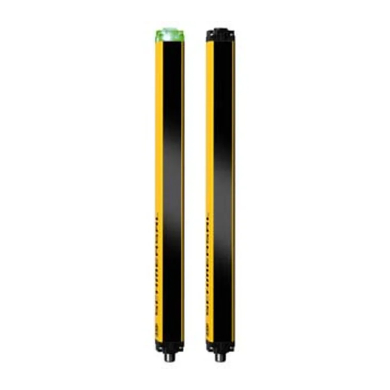
Features of the safety light grid Type 4 Safeguards protected fields with body resolution Muting All safety light grids in the PSEN op4B/1 Series are able to process data from connec- ted muting sensors Infrared protected field is generated Transmitter and receiver are synchronised optically... - Page 10 Legende [1] Receiver [2] Transmitter [3] LED on receiver/transmitter [4] Height of the protected field [5] Width of the protected field [6] 8-pin and 5-pin connector of receiver [7] 4-pin and 5-pin connector of transmitter Operating Manual PSEN op4B/1 Series 1003356-EN-02...
-
Page 11: Safety Light Grid With Integrated Muting Sensors
4-pin connector of muting sensors for connection to receiver/transmitter L-muting application Use L-type with muting sensors in one direction when material is moved through the danger zone from one direction PSEN op4B-L-050/1 PSEN op4B-L-080/1 Operating Manual PSEN op4B/1 Series 1003356-EN-02... - Page 12 B1 Position of the second light beam on the muting sensor T-muting application Use T-types with muting sensors in two directions when material is moved through the danger zone from two directions PSEN op4B-T-050/1 PSEN op4B-T-080/1 Operating Manual PSEN op4B/1 Series 1003356-EN-02...
-
Page 13: Scope
Scope Safety light grid with body resolution, without integrated muting sensors Order reference Description PSEN op4B-2-050/1 or Safety light grid, consisting of PSEN op4B-3-080/1 or Transmitter PSEN op4B-4-090/1 or Receiver PSEN op4B-4-120/1 Mounting kit Operating Manual PSEN op4B/1 Series 1003356-EN-02... - Page 14 Order reference Description PSEN op4B-T-050/1 or Safety light grid, consisting of PSEN op4B-T-080/1 Transmitter Receiver Mounting kit 4 integrated muting sensors Cable for connecting the muting sensors Mounting kit for muting sensors Operating Manual PSEN op4B/1 Series 1003356-EN-02...
-
Page 15: Safety
Safety Safety Intended use Safety light grids in the PSEN op4B/1 Series constitute electrosensitive protective equip- ment. They are used to protect personnel and plants. The safety light grids are designed to Safeguards protected fields with body resolution Safeguard danger zones and Safeguard access. -
Page 16: Use Of Qualified Personnel
In safety-related applications, please comply with the mission time T in the safety-re- lated characteristic data. When decommissioning, please comply with local regulations regarding the disposal of electronic devices (e.g. Electrical and Electronic Equipment Act). Operating Manual PSEN op4B/1 Series 1003356-EN-02... -
Page 17: Function Description
55]. 4.1.1 Function settings when delivered The safety light grid is delivered with all DIP switches in the ON position. Fig.: DIP switches all ON As a result the functions are set as follows: Operating Manual PSEN op4B/1 Series 1003356-EN-02... -
Page 18: Restart After Safety Light Grid Is Activated
It must not be possible to operate the pushbutton from inside the danger zone. The button must be located at a position from which there is a full, un- obstructed view of the danger zone. Operating Manual PSEN op4B/1 Series 1003356-EN-02... -
Page 19: Reset Function
In order to restore normal operating con- ditions, the safety light grid must be reset. Internal errors are: Malfunction of the outputs or Optical malfunction or Malfunction of the muting display or Incorrect operation of the EDM function. Operating Manual PSEN op4B/1 Series 1003356-EN-02... -
Page 20: Edm
If a malfunction is de- tected, the safety light grid switches to a safe condition and stops the connected machine. This check is carried out each time the OSSD is triggered and before restarting. Operating Manual PSEN op4B/1 Series 1003356-EN-02... -
Page 21: Muting
Muting proves to be particularly suitable when, under certain operating conditions, an object is permitted to pass through the danger zone but a person is not. The following diagrams illustrate application examples for the three product types. Operating Manual PSEN op4B/1 Series 1003356-EN-02... - Page 22 Function description Fig.: L-type muting in one direction (integrated muting sensors) Fig.: T-type muting in two directions (integrated muting sensors) Operating Manual PSEN op4B/1 Series 1003356-EN-02...
-
Page 23: Technical Implementation
– when the first sensor has detected a conveyed material and the second sensor also detects it max. 4 s afterwards. Operating Manual PSEN op4B/1 Series 1003356-EN-02... - Page 24 If the muting lamp is defective, the muting function cannot be activated. Any attempt to activate the function will immediately trigger the safety light grid and instantly switch off the OSSD; the muting lamp fault indicator will also light (seeIndicators for fault diagnostics [ 55]). Operating Manual PSEN op4B/1 Series 1003356-EN-02...
- Page 25 : Once this time has elapsed, the muting function switches off automatically, max. 8 s Moff Input Muting 1 Input Muting 2 Muting function Fig.: Timing diagram for T-type muting Legend : Time from the activation of the first sensor to the activation of the second sensor, max. 4 s Operating Manual PSEN op4B/1 Series 1003356-EN-02...
-
Page 26: Time Monitoring - Timeout
If the muting sensors are still active after 10 minutes (status when delivered), the muting status is cancelled and the safety light grid switches to a safe condition. Operating Manual PSEN op4B/1 Series 1003356-EN-02... -
Page 27: Override
Fig.: Timing diagram for override function A key or automatic reset button is provided for activation. Position the key or pushbutton so that when the override function is activated nobody can reach the danger zone and Operating Manual PSEN op4B/1 Series 1003356-EN-02... -
Page 28: Test Function
The test function can be used to test the safety light grid. The reaction of the safety light grid corresponds to the reaction when a protected field is violated, but can be triggered by pressing the TEST/START button. Operating Manual PSEN op4B/1 Series 1003356-EN-02... -
Page 29: Convert Type Without Muting Sensors To L/T-Type
Fig.: Timing diagram for test function Convert type without muting sensors to L/T-type The safety light grids in the PSEN op4B/1 Series series are already capable of processing the data from muting sensors and can be upgraded to L or T-types using the muting sensors available as accessories. -
Page 30: Project Configuration
Avoid strong electromagnetic interference when operating the safety light grid. When operating the safety light grid, avoid the development of smoke, mist and dust that would reduce the operating range of the safety light grid. Operating Manual PSEN op4B/1 Series 1003356-EN-02... -
Page 31: Distance From Reflective Surfaces
The formula for calculating the minimum distance D for a safety light grid is: Operating range < 3 m: 0.15 m Operating range ≥ 3 m: 0.5 x D in m x tan 2α Operating Manual PSEN op4B/1 Series 1003356-EN-02... -
Page 32: Installation Of Several Adjacent Safety Light Grids
Fig.: Non-permitted layout of two adjacent safety light grids Positioning of several adjacent safety light grids: Both safety light grids must be oriented in opposite directions or An opaque surface must be positioned between two safety light grids. Operating Manual PSEN op4B/1 Series 1003356-EN-02... -
Page 33: Use Of Deviating Mirrors
The diagram below shows an example solution for monitoring three different access sides using two deviating mirrors. The deviating mirrors must be positioned at an angle of 45° to the beams from the safety light grid. Operating Manual PSEN op4B/1 Series 1003356-EN-02... - Page 34 Please consider this reduction when positioning the safety light grid. You should not use more than three mirrors per device. Any dust or dirt on the mirror’s reflective surface will drastically reduce the operating range. Operating Manual PSEN op4B/1 Series 1003356-EN-02...
-
Page 35: Use Of The Muting Function
The sign should indicate that there is no protection when the muting lamp is lit. Please note the following distances and times when installing the safety light grid and using the muting function. Operating Manual PSEN op4B/1 Series 1003356-EN-02... - Page 36 [1] Safety light grid A1 First muting sensor on the input side B1 Second muting sensor on the input side A2 First muting sensor on the output side B2 Second muting sensor on the output side Operating Manual PSEN op4B/1 Series 1003356-EN-02...
- Page 37 4.125 Speed at which the object is moving < D Distance must be Distance between the mut- MutingOff covered within 4 s ing sensors A1 and B1 Operating Manual PSEN op4B/1 Series 1003356-EN-02...
- Page 38 A1 to the second muting sensor Distance between activation of MutingOff the muting function and the position from which the muting function is switched off again Distances for cross muting with 2 sensors Operating Manual PSEN op4B/1 Series 1003356-EN-02...
-
Page 39: Installation And Wiring
Attach the mounting profile to the safety light grid (see drawing). Use the hexagonal screws to fix the mounting profile in the position required for using the muting sensors. Screw in the screws in the middle of the slot hole. Operating Manual PSEN op4B/1 Series 1003356-EN-02... -
Page 40: Conversion Of Safety Light Grids Without Muting Sensors
To do this, loosen the hexagonal screws. Then tighten up the hexagonal screws again. The mounting profiles should be at the same height. [1] Mounting profile for attaching the muting sensor [2] Safety light grid on mounting surface Operating Manual PSEN op4B/1 Series 1003356-EN-02... -
Page 41: Installation Of External Muting Sensors
Connect the N/C contact on the EDM to the supply voltage on the safety light grid. The safety light grid is already equipped with internal filter capacitors. We would advise against using additional external components. Operating Manual PSEN op4B/1 Series 1003356-EN-02... -
Page 42: Connector Pin Assignment
PIN Designation Description Cable colour 1 TEST/RESET TEST/START button White 2 +24 VDC Supply voltage for receiver on the safety light Brown grid 3 Override 1 N/O contact to override muting sensor input Green Operating Manual PSEN op4B/1 Series 1003356-EN-02... - Page 43 Fig.: 5-pin connector on the transmitter to connect the supply voltage for muting sensors to the trans- mitter on the safety light grid PIN Designation Description Cable colour +24 VDC Supply voltage for external muting sensor Brown n.c. White 0 VDC Supply voltage for external muting sensor Blue n.c. Black Operating Manual PSEN op4B/1 Series 1003356-EN-02...
-
Page 44: Test/Start Button
Identify the earthing contact using the adhesive label provided. Legend: [1]: Drill holes for earthing screw. The drill holes are on the bottom of the safety light grid, at the same height on the right and left. Operating Manual PSEN op4B/1 Series 1003356-EN-02... -
Page 45: Connections For Muting
Fig.: Wiring of 2 muting sensors on the receiver's 5-pin connector Muting sensor Safety light grid Muting A1 Muting B2 Fig.: Wiring of 2 muting sensors for cross muting on the receiver's 5-pin connector Operating Manual PSEN op4B/1 Series 1003356-EN-02... -
Page 46: Wiring Of External Sensors On The Safety Light Grid
Identify the earthing contact using the adhesive label provided. 6.5.7 Wiring of external sensors on the safety light grid Wire the external muting sensors in the control cabinet in accordance with the details stated under Connections for muting. Operating Manual PSEN op4B/1 Series 1003356-EN-02... -
Page 47: Commissioning
To use muting, the following requirements apply: the muting lamp must not be defective, the muting inputs must be wired correctly (see Connector pin assignment [ 42]), the safety light grid must be in normal operation. Operating Manual PSEN op4B/1 Series 1003356-EN-02... -
Page 48: Set Muting Timeout
Restart after unit is triggered Select how the restart is controlled after the OSSDs have been switched off. Without restart interlock Status when delivered With restart interlock Set DIP switches 4 and 8 to OFF. Operating Manual PSEN op4B/1 Series 1003356-EN-02... -
Page 49: Orientation
Align [4] will light If both beams are aligned correctly and the LEDs are lit, the green LED will also light [1] The alignment of a type without muting set is described under Safety light grid alignment. Operating Manual PSEN op4B/1 Series 1003356-EN-02... -
Page 50: Safety Light Grid Alignment
If a single light beam is interrupted by an opaque object – the green LED must go out, – the red LED must light and – the safety light grid must switch to a safe condition. Operating Manual PSEN op4B/1 Series 1003356-EN-02... -
Page 51: Muting Sensor Alignment
Legend: [1]: Move the muting sensor upwards on the mounting profile for vertical alignment [2]: Move the muting sensor within the slot hole for horizontal alignment Operating Manual PSEN op4B/1 Series 1003356-EN-02... -
Page 52: Led Support During Alignment
Maintaining the safety distance. If muting sensors are installed: Check that the muting sensors operate correctly. Access the protected field covered by the muting sensors. – The muting lamp on the safety light grid must light. Operating Manual PSEN op4B/1 Series 1003356-EN-02... -
Page 53: System Connection
This section provides information on how to connect the safety light grid to an evaluation device. A safety relay from the PNOZsigma series (PNOZ s4, PNOZ s5) can be used as the evalu- ation device, for example. The wiring is described in the operating instructions for the PNOZsigma device. Operating Manual PSEN op4B/1 Series 1003356-EN-02... -
Page 54: Operation
Normal Override can be performed. Opera- Activate the override function and tion make sure that the protected field is clear. OSSD Lights Restart/ Flashes Align yellow Align LED indicators during normal operation - Receiver Operating Manual PSEN op4B/1 Series 1003356-EN-02... -
Page 55: Perform Test
Switch the safety light grid off and then on again. If the display is un- changed, swap the ex- ternal switching device. Operating Manual PSEN op4B/1 Series 1003356-EN-02... - Page 56 [ 62]) details [ 62]. green Switch the safety light grid off and then on Flashes again. yellow If the display is un- changed, contact Pilz. LED indicators in fault condition - Receiver Operating Manual PSEN op4B/1 Series 1003356-EN-02...
-
Page 57: Perform Reset
There must be nobody within the danger zone Procedure Press the TEST/START button for at least 5 seconds and then release it. The OSSDs switch on, the green LED lights and the connected machine starts up. Operating Manual PSEN op4B/1 Series 1003356-EN-02... -
Page 58: Regular Checks And Maintenance
The Appendix contains a Checklist which should help you perform the safety check. Maintenance Other than cleaning the lens covers, the safety light grids requires no other form of main- tenance. CAUTION! Improper cleaning agents can damage the safety light grid and lead to mal- functions Operating Manual PSEN op4B/1 Series 1003356-EN-02... - Page 59 Moist cotton cloths should be used for cleaning. Avoid using Alcohol Solvents, Cloths made of wool, Cloths made of synthetic material. The lens covers should be cleaned during the daily check of hte safety light grid. Operating Manual PSEN op4B/1 Series 1003356-EN-02...
-
Page 60: Dimensions
Dimensions Dimensions Safety light grid without integrated muting sensors M12x1 Fig.: Receiver M12x1 Fig.: Transmitter Legende [1] Height of protected field [2] Position of first light beam [3] Position of last light beam Operating Manual PSEN op4B/1 Series 1003356-EN-02... - Page 61 Dimensions Safety light grid with L-muting set 44,1 Safety light grid with T-muting set 44,1 655,1 Operating Manual PSEN op4B/1 Series 1003356-EN-02...
-
Page 62: Technical Details
In accordance with the standard EN 60068-2-6 EN 60068-2-6 Frequency 10 - 55 Hz 10 - 55 Hz 0,35 mm 0,35 mm Amplitude Shock stress In accordance with the standard EN 60068-2-29 EN 60068-2-29 Acceleration Duration 16 ms 16 ms Operating Manual PSEN op4B/1 Series 1003356-EN-02... - Page 63 Switching current per output 500 mA 500 mA Times 630802 630803 16 ms 16 ms Response time t1 Environmental data 630802 630803 Ambient temperature Temperature range -10 - 55 °C -10 - 55 °C Operating Manual PSEN op4B/1 Series 1003356-EN-02...
- Page 64 Sensor's mode of operation optical optical 515 mm 815 mm Height of detection zone Resolution Protection type Body Body 0,5 - 3 m 0,5 - 3 m Operating range Resolution of protected field 515 mm 415 mm Operating Manual PSEN op4B/1 Series 1003356-EN-02...
- Page 65 M12, 5-pin male connector; M12, M12, 5-pin male connector; M12, 8-pin male connector 8-pin male connector M12, 4-pin male connector; M12, M12, 4-pin male connector; M12, Transmitter 5-pin male connector 5-pin male connector Material Aluminium Aluminium Operating Manual PSEN op4B/1 Series 1003356-EN-02...
- Page 66 In accordance with the standard EN 60068-2-6 EN 60068-2-6 Frequency 10 - 55 Hz 10 - 55 Hz 0,35 mm 0,35 mm Amplitude Shock stress In accordance with the standard EN 60068-2-29 EN 60068-2-29 Acceleration Duration 16 ms 16 ms Operating Manual PSEN op4B/1 Series 1003356-EN-02...
-
Page 67: Safety Characteristic Data
A safety function's SIL/PL values are not identical to the SIL/PL values of the units that are used and may be different. We recommend that you use the PAScal software tool to calculate the safety function's SIL/PL values. Operating Manual PSEN op4B/1 Series 1003356-EN-02... -
Page 68: Order Reference
630 953 Column-165/1 PSEN op Protective Protective column for safety light grid, H = 1900 mm 630 954 Column-190/1 PSEN op Protective Base/1 Floor bracket 630 955 PSEN op Bracket kit antivibra- Vibration damper 630 327 tion Operating Manual PSEN op4B/1 Series 1003356-EN-02... - Page 69 Connection cable for light beam devices, 8‑pole, shiel- 630 328 shield. 30m ded, 30 m PSEN op cable axial M12 8-p. Connection cable for light beam devices, 8‑pole, shiel- 630 368 shield. 50m ded, 50 m Operating Manual PSEN op4B/1 Series 1003356-EN-02...
- Page 70 Mounting bracket for one muting sensor 630 824 PSEN op cable M12 4-p. 0.75m Connection cable for L-muting, 630 282 L-muting 4‑core, shielded PSEN op cableset Connection cable for T-muting, 630 295 4‑core, shielded Operating Manual PSEN op4B/1 Series 1003356-EN-02...
- Page 71 Has the minimum distance been calculated in accordance with the applicable stand- ards? Has the calculated minimum distance been maintained at all points? Check protected field Has the ability to creep underneath the pro- tected field undetected been excluded? Operating Manual PSEN op4B/1 Series 1003356-EN-02...
- Page 72 When you switch on, is it necessary to oper- ate the control device for the start-up inter- lock before the plant/machine can start up? Switch off safety light grid Is the hazardous movement stopped imme- diately when you switch off? Operating Manual PSEN op4B/1 Series 1003356-EN-02...
- Page 73 Check guard function for protected field of the safety light grid: Violate the protected field at various points: The hazardous movement must be shut down. Check that the start/restart interlock is work- ing correctly. Operating Manual PSEN op4B/1 Series 1003356-EN-02...
- Page 74 Back cover Support Technical support is available from Pilz round the clock. Americas Australia Scandinavia Brazil +61 3 95446300 +45 74436332 +55 11 97569-2804 Spain Canada Europe +34 938497433 +1 888-315-PILZ (315-7459) Austria Switzerland +41 62 88979-30 Mexico +43 1 7986263-0...
Need help?
Do you have a question about the PSEN op4B/1 Series and is the answer not in the manual?
Questions and answers