Table of Contents
Advertisement
Quick Links
Advertisement
Table of Contents

Related Manuals for Pilz PSEN ma1.4p-51


Summary of Contents for Pilz PSEN ma1.4p-51
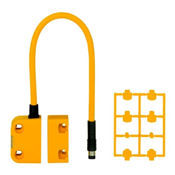
- Page 1 PSEN ma1.4p-51 PSEN sensor technology Operating Manual-22127-EN-05...
- Page 2 Preface This document is a translation of the original document. All rights to this documentation are reserved by Pilz GmbH & Co. KG. Copies may be made for internal purposes. Suggestions and comments for improving this documentation will be gratefully received.
-
Page 3: Table Of Contents
Wiring Pin assignment Requirements and connection to evaluation devices Installation Installation type 1 Installation type 2 Adjustment Periodic test Dimensions in mm Technical details Safety characteristic data Order reference System Accessories EC declaration of conformity Operating Manual PSEN ma1.4p-51 22127-EN-05... -
Page 4: Introduction
PSEN ma1.4p-51 Introduction Validity of documentation This documentation is valid for the product PSEN ma1.4p-51. It is valid until new document- ation is published. This operating manual explains the function and operation, describes the installation and provides guidelines on how to connect the product. -
Page 5: Safety
In order to achieve the re- quired safety level for the overall plant/machine, define the safety requirements for the plant/machine and then define how these must be implemented from a technical and organ- isational standpoint. Operating Manual PSEN ma1.4p-51 22127-EN-05... -
Page 6: Use Of Qualified Personnel
– If spare actuators are used, these must be installed as described in Installation [ 14]. – If the original actuators are replaced with substitute actuators, the ori- ginal actuators must be destroyed before disposal. Operating Manual PSEN ma1.4p-51 22127-EN-05... -
Page 7: Unit Features
If the actuator is within the response range (safety gate closed), the safety contacts and the auxiliary contact on the safety switch will be closed and the LED will light. Operate the PSEN ma1.4p-51 in conjunction with the following components: Actuator PSEN ma1.4-03 or actuator PSEN ma1.4-10 (see... -
Page 8: Block Diagram
Block diagram Safety switch Actuator Magnet Operating distances (mm) omin Legend Assured operating distance Min. operating distance omin Assured release distance The offset-independent values for the switching distances are included in the Technical details [ 18]. Operating Manual PSEN ma1.4p-51 22127-EN-05... -
Page 9: Lateral And Vertical Offset
Lateral offset Vertical offset 0 mm 2 mm 4 mm 6 mm 8 mm 0 mm 10.0 10.0 2 mm 10.0 10.0 4 mm 6 mm The stated values are valid at a temperature of 20 °C. Operating Manual PSEN ma1.4p-51 22127-EN-05... -
Page 10: Wiring
Pin assignment NOTICE The colour marking for the connection lead only applies for the cable that Pilz supplies as an accessory The safety switch is shown in an unoperated condition. pink Assignment of... -
Page 11: Requirements And Connection To Evaluation Devices
PNOZmulti units – may not be used for safety circuits Requirements and connection to evaluation devices For use of PSEN ma1.4p-51 in accordance with DIN EN 60947-5-3 an evaluation device must be connected. Connect the PSEN ma1.4p-51 either with a certified Pilz evaluation device... - Page 12 18]) and the processing and delay times of the evaluation device (s. operating manual for the relevant evaluation device). Evaluation device PSENmag Input circuit Input circuit Fig.: Dual-channel connection PSEN ma1.4p-51 to the input circuits of an evaluation device Operating Manual PSEN ma1.4p-51 22127-EN-05...
- Page 13 PSEN ma1.4p-51 Examples for connection to Pilz evaluation devices: PNOZ s3 PSENmag Pink green white yellow PNOZmulti PSENmag Pink green white yellow Auxiliary contact with LED The auxiliary contact and the LED indicate the status of the safety contacts. Safety contacts and auxili-...
-
Page 14: Installation
The fastening of safety switch and actuator has to be sufficiently stable to ensure the proper operation of the safety switch and the actuator. The distance between two safety switches must be maintained (see Technical details [ 18]). Operating Manual PSEN ma1.4p-51 22127-EN-05... - Page 15 9. Close unused mounting holes using seal (2) (see Diagram [ 16]). 10. Close mounting holes on the sensing face using seal (3) (see Diagram [ 16]). 11. Installation of sensor and actuator is now complete. Operating Manual PSEN ma1.4p-51 22127-EN-05...
-
Page 16: Installation Type 2
4. Align actuator and tighten screws with max. 0,8 Nm. 5. Close used mounting holes using seal (1) or (4) (see Diagram [ 17]). 6. Close mounting holes on the sensing face using seal (3) (see Diagram [ 17]). Operating Manual PSEN ma1.4p-51 22127-EN-05... -
Page 17: Adjustment
Lateral and vertical offset [ 8]). Periodic test Carry out a monthly function test on the safety switch and actuator. Always test the function with a connected evaluation device. The safety function may only be checked by qualified personnel. Operating Manual PSEN ma1.4p-51 22127-EN-05... -
Page 18: Dimensions In Mm
Voltage tolerance -20 %/+20 % -20 %/+20 % Max. switching frequency 1 Hz 1 Hz 1 mA 1 mA Lowest operating current (Im) Switching voltage 24 V 24 V Internal resistance 10 Ohm 10 Ohm Operating Manual PSEN ma1.4p-51 22127-EN-05... - Page 19 Typical release distance Sr 6 mm 16 mm Repetition accuracy switching distances Min. distance between safety 50 mm 50 mm switches Sensor flush installation in accord- Yes, follow installation Yes, follow installation ance with EN 60947-5-2 guidelines guidelines Operating Manual PSEN ma1.4p-51 22127-EN-05...
-
Page 20: Safety Characteristic Data
3 mm PSEN ma1.4p-51/ Magnetic safety switch, actu- 8-pin M8 male connector 506 338 PSEN ma1.4-10mm/ ator with assured operating 1unit distance 10 mm PSEN ma1.4p-51/ Magnetic safety switch 8-pin M8 male connector 506 310 1switch Operating Manual PSEN ma1.4p-51 22127-EN-05... -
Page 21: Accessories
European Parliament and of the Council. The complete EC Declaration of Conformity is available on the Internet at www.pilz.com/downloads. Representative: Norbert Fröhlich, Pilz GmbH & Co. KG, Felix-Wankel-Str. 2, 73760 Ost- fildern, Germany Operating Manual PSEN ma1.4p-51... - Page 22 Back cover Support Technical support is available from Pilz round the clock. Americas Australia Scandinavia Brazil +61 3 95600621 +45 74436332 +55 11 97569-2804 Spain Canada Europe +34 938497433 +1 888-315-PILZ (315-7459) Austria Switzerland +41 62 88979-30 Mexico +43 1 7986263-0...
Need help?
Do you have a question about the PSEN ma1.4p-51 and is the answer not in the manual?
Questions and answers