Table of Contents
Advertisement
Quick Links
AN620
BGT60ATR24C ES shield
XENSIV™ 60 GHz radar system platform
B o a r d v e r s i o n V 2 . 0
About this document
Scope and purpose
This application note describes the function, circuitry, and performance of the BGT60ATR24C shield
(SHIELD_60ATR24ES_01) , part of Infineon's XENSIV™ 60 GHz radar system platform. The shield provides the
supporting circuitry to the on-board BGT60ATR24C monolithic microwave integrated circuit (MMIC) Infineon's
60 GHz radar chipset with external antennas. The shield offers a digital interface for configuration and transfer
of the acquired radar data to a microcontroller board, e.g., Radar Baseboard MCU7.
The MMIC-related parameters mentioned in the document are based on engineering samples (ES).
Intended audience
The intended audience for this document are design engineers, technicians, and developers of electronic
systems, working with Infineon's XENSIV™ 60 GHz radar sensors, especially in automotive scenarios called in-
cabin sensing (ICMS). Among the many applications it can be used for are– rear occupancy alert (ROA) and – left
behind child (LBC) systems.
Related documents
Additional information can be found in the documentation provided with the
Radar Development Kit
tool in the
Infineon Developer Center
(IDC), or from www.infineon.com/60GHz.
Application note
Please read the sections "Important notice" and "Warnings" at the end of this document
Revision 1.10
www.infineon.com
2023-02-14
Advertisement
Table of Contents

Related Manuals for Infineon BGT60ATR24C


Summary of Contents for Infineon BGT60ATR24C
-
Page 1: About This Document
This application note describes the function, circuitry, and performance of the BGT60ATR24C shield (SHIELD_60ATR24ES_01) , part of Infineon’s XENSIV™ 60 GHz radar system platform. The shield provides the supporting circuitry to the on-board BGT60ATR24C monolithic microwave integrated circuit (MMIC) Infineon’s 60 GHz radar chipset with external antennas. -
Page 2: Table Of Contents
BGT60ATR24C ES shield XENSIV™ 60 GHz radar system platform Table of contents Table of contents About this document ........................1 Table of contents ..........................2 Introduction .......................... 3 60 GHz radar system platform ........................ 3 Key features ............................. 3 System specifications ......................4 Typical power consumption ........................ -
Page 3: Introduction
60 GHz radar system platform The 60 GHz radar system platform is the demo platform for Infineon’s 60 GHz radar solutions. It consists of the Radar Baseboard MCU7 as the microcontroller board and a radar sensor board, like the BGT60ATR24C shield for Infineon’s 60 GHz radar sensor chip. -
Page 4: System Specifications
The typical power consumption of the whole 60 GHz radar sensor platform, consisting of a Radar Baseboard MCU7 and a BGT60ATR24C shield, can be found in Table 1 and Table 2. The microcontroller on the Radar Baseboard MCU7 will change its mode of operation depending on the sensor that is plugged in and the signal processing that is required. -
Page 5: Hardware Description
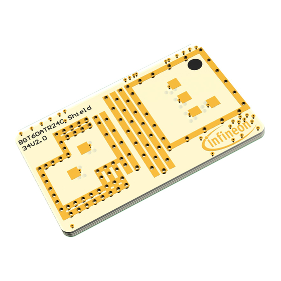
Top and bottom views of the BGT60ATR24C shield The dimensions of the BGT60ATR24C shield are 26 mm x 16 mm. The BGT60ATR24C sensor is mounted on top of the PCB, while on the bottom patch antennas have been located. The current design of the shield uses two Rogers laminate layers for top and bottom (RO3003 top and RO4350B bottom). -
Page 6: Oscillator
NDK NZ2520SHA. The R6 series resistor reduces the RF level at the sensor so that it is at the optimal range for the BGT60ATR24C. If a redesign of the board contains a different signal source or a vastly different layout is implemented, the value of R1 (150 Ω) may... -
Page 7: Connectors
Figure 5 describes the pin-out and the pad layout of the Hirose connectors on the BGT60ATR24C shield. To provide the information of the correct digital signal level to the host board, the line Vdigital is shorted with the 1.8 V supply. The RF shield and the MCU7 board have to be properly aligned, as depicted in Figure 1. -
Page 8: Layer Stackup
Layer 1. Layer 3 consists of signal lines and power planes with the voltage domains required for BGT60ATR24C and other components. Layer 4 is the ground plane for the antennas that are placed on layer 5. Figure 8 Layer 1 –... - Page 9 BGT60ATR24C ES shield XENSIV™ 60 GHz radar system platform Hardware description Figure 9 Layer 2 – GND plane for component side Figure 10 Layer 3 – signal/power layer Figure 11 Layer 4 – GND plane for antenna side Figure 12 Layer 5 –...
-
Page 10: Layout Overview
Lines to the feed-throughs to the antenna side • The matching structures transform BGT60ATR24C’s chip impedances at the package side into 50 . The transmission lines to the feed-throughs correct for phase differences between the channels (see section 5.1) so that all RX channels and TX channels are in phase at the antenna side. - Page 11 BGT60ATR24C ES shield XENSIV™ 60 GHz radar system platform Layout overview Figure 14 Bottom layer overview, antenna side RX1 RX3 Figure 15 Antenna naming TX antennas RX antennas Physical antennas 3x4 virtual antenna array Figure 16 MIMO antenna array Application note Revision 1.10...
-
Page 12: Tx And Rx Channels
TX and Rx channels TX and Rx channels Phase relationship between RF channels Due to BGT60ATR24C device’s topology, the phase between single channels is partly shifted by 180° 5.1.1 TX outputs The TX outputs have a phase difference of 180°, as shown in Figure 17. -
Page 13: Measurement Results
All measurements include the feed-throughs from the top layer. The achieved bandwidth here is over 4 GHz. The antennas’ center frequency is shifted to higher frequencies but can be moved to the center of the BGT60ATR24C MMIC’s frequency band by fine tuning. Figure 19... -
Page 14: System Radiation Characteristics
The received amplitudes were normalized to the peak value of the respective cut plane considering data from every RX channel. The plots show that the system works well over the BGT60ATR24C MMIC’s entire frequency range. The antennas will still need some fine tuning, especially RX2. - Page 15 BGT60ATR24C ES shield XENSIV™ 60 GHz radar system platform Measurement results Figure 22 Amplitudes received by RX1 over angle, polarizations, transmitters, and frequency Application note Revision 1.10 2023-02-14...
- Page 16 BGT60ATR24C ES shield XENSIV™ 60 GHz radar system platform Measurement results Figure 23 Amplitudes received by RX2 over angle, polarizations, transmitters, and frequency Application note Revision 1.10 2023-02-14...
- Page 17 BGT60ATR24C ES shield XENSIV™ 60 GHz radar system platform Measurement results Figure 24 Amplitudes received by RX3 over angle, polarizations, transmitters, and frequency Application note Revision 1.10 2023-02-14...
- Page 18 BGT60ATR24C ES shield XENSIV™ 60 GHz radar system platform Measurement results Figure 25 Amplitudes received by RX4 over angle, polarizations, transmitters, and frequency Application note Revision 1.10 2023-02-14...
-
Page 19: References
BGT60ATR24C ES shield XENSIV™ 60 GHz radar system platform References References Infineon Technologies AG. AN599: Radar Baseboard MCU7 Committee, E. C. (n.d.). ERC Recommendation. Retrieved 03 12, 2019, from https://www.ecodocdb.dk/download/25c41779-cd6e/Rec7003.pdf European Telecommunications Standards Institute. (n.d.). Retrieved 03 12, 2019, from https://www.etsi.org/... -
Page 20: Revision History
BGT60ATR24C ES shield XENSIV™ 60 GHz radar system platform Revision history Revision history Document Date Description of changes revision 1.00 2022-11-08 Initial version 1.10 2023-02-14 Miscellaneous document cleanup updates Application note Revision 1.10 2023-02-14... -
Page 21: Disclaimer
Infineon Technologies hereby Infineon Technologies’ products may not be used in disclaims any and all warranties and liabilities of any applications where a failure of the product or any any kind (including without limitation warranties of © 2023 Infineon Technologies AG.
Need help?
Do you have a question about the BGT60ATR24C and is the answer not in the manual?
Questions and answers