Table of Contents
Advertisement
Quick Links
AN605
Using Infineon's radar baseboard XMC4700 and
BGT24LTR11 radar shield with Arduino
Set-up guide
About this document
Scope and purpose
This application note provides a step-by-step guide to setting up Infineon's 24 GHz Sense2GoL Pulse radar
system platform, which is made up of the radar baseboard XMC4700 and BGT24LTR11 radar shield, making up
the hardware and software for use with the Arduino platform. This guide will then go on to show an application
example to demonstrate some of the features of this radar system platform.
Intended audience
This document is intended for anyone interested in using Infineon's 24 GHz radar system platform with the
Arduino platform.
Related documents
Additional information can be found in the supplementary documentation provided with the Sense2GoL Pulse
Kit in the Infineon Toolbox or from www.infineon.com/24GHz:
24 GHz Radar Tools and Development Environment User Manual
Sense2GoL Pulse Software User Manual
AN 598 – BGT24LTR11 Shield (Pulsed Doppler)
AN602 – Radar Baseboard XMC4700
www.infineon.com
Please read the Important Notice and Warnings at the end of this document
page 1 of 31
2019-12-02
Advertisement
Table of Contents

Related Manuals for Infineon XMC4700


Summary of Contents for Infineon XMC4700
-
Page 1: About This Document
This application note provides a step-by-step guide to setting up Infineon’s 24 GHz Sense2GoL Pulse radar system platform, which is made up of the radar baseboard XMC4700 and BGT24LTR11 radar shield, making up the hardware and software for use with the Arduino platform. This guide will then go on to show an application example to demonstrate some of the features of this radar system platform. -
Page 2: Table Of Contents
Using Infineon’s radar baseboard XMC4700 and BGT24LTR11 radar shield with Arduino Set-up guide Table of contents Table of contents About this document ........................1 Table of contents ..........................2 List of figures ..........................3 List of tables ..........................4 Introduction .......................... 5 Hardware modifications ...................... -
Page 3: List Of Figures
Figure 27 Attach the BGT24LTR11 shield to the radar baseboard XMC4700 ........... 22 Figure 28 Stacking the RGB LED lighting shield onto the radar baseboard XMC4700 ........23 Figure 29 Stacking the Annikken Andee U shield onto the set-up ..............23 Figure 30 Jumper wire connections on the Andee U .................. -
Page 4: List Of Tables
Using Infineon’s radar baseboard XMC4700 and BGT24LTR11 radar shield with Arduino Set-up guide List of tables List of tables Table 1 Configuration APIs ..........................13 Table 2 Result APIs ............................14 Table 3 Control APIs ............................16 Table 4 Example sketches ..........................17 Table 5 LED color based on motion for Example 1 .................. -
Page 5: Introduction
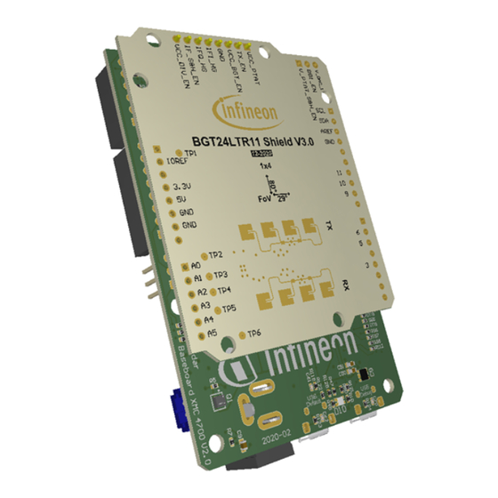
Introduction Introduction The radar baseboard XMC4700, which is part of Infineon’s 24 GHz radar system platform, is designed with headers compatible with Arduino (Figure 1) to ease prototyping works and integration with other Arduino shields in the market to form a compelling application. - Page 6 Using Infineon’s radar baseboard XMC4700 and BGT24LTR11 radar shield with Arduino Set-up guide Introduction Figure 2 BGT24LTR11 radar shield For more details on the features of each board, please refer to their respective documents as mentioned on the cover page of this document.
-
Page 7: Hardware Modifications
C communication Selection of IOREF XMC4700 operates in the 3.3 V domain. Depending on the target Arduino shield, the IOREF can be configured as 5 V or 3.3 V via a jumper on P2 (Figure 4). To select 3.3 V as IOREF, short pins 1 and 2 of P2. -
Page 8: Iscp Header
Using Infineon’s radar baseboard XMC4700 and BGT24LTR11 radar shield with Arduino Set-up guide Hardware modifications Figure 4 Jumper selection for IOREF ISCP header In case connection via the ISCP header is required to the target Arduino shield, do not use the pins from header P7. -
Page 9: Software Set-Up
Set-up guide Software set-up Software set-up This section highlights the steps needed in order to use Infineon’s 24 GHz radar system platform with the Arduino IDE. Download and install Arduino IDE The first step is to download the latest Arduino IDE version from https://www.arduino.cc/en/main/software... - Page 10 Using Infineon’s radar baseboard XMC4700 and BGT24LTR11 radar shield with Arduino Set-up guide Software set-up Figure 7 Arduino IDE: File > Preferences Figure 8 Entering the location from which the package can be downloaded 10 of 31 2019-12-02...
- Page 11 Using Infineon’s radar baseboard XMC4700 and BGT24LTR11 radar shield with Arduino Set-up guide Software set-up Figure 9 Installing the XMC package Figure 10 Selecting XMC baseboard 11 of 31 2019-12-02...
-
Page 12: Using Pulsed Doppler Radar Library
Using Infineon’s radar baseboard XMC4700 and BGT24LTR11 radar shield with Arduino Set-up guide Software set-up Using Pulsed Doppler Radar Library The Pulsed Doppler Radar Library is installed as part of the core libraries for XMC when the XMC Arduino package is installed as shown in Section 3.2. - Page 13 Using Infineon’s radar baseboard XMC4700 and BGT24LTR11 radar shield with Arduino Set-up guide Software set-up Next, some steps are required to initialize the hardware for the Pulsed Doppler Radar and also to configure the parameters. All these are to be done within the setup() routine (Figure 13).
- Page 14 Using Infineon’s radar baseboard XMC4700 and BGT24LTR11 radar shield with Arduino Set-up guide Software set-up API name Description Retrieve threshold that will determine motion with float getDopplerSensitivity(void); direction (departing/approaching) or not Set frame period in µs uint8_t setFramePeriod(uint8_t periodUs); Retrieve configured frame period in µs uint8_t getFramePeriod(void);...
- Page 15 Using Infineon’s radar baseboard XMC4700 and BGT24LTR11 radar shield with Arduino Set-up guide Software set-up Figure 14 Example for callback function definition Finally, add the run() API in the loop() routine to run the radar processing (Figure 15). 15 of 31...
-
Page 16: Example Sketches
Using Infineon’s radar baseboard XMC4700 and BGT24LTR11 radar shield with Arduino Set-up guide Software set-up Figure 15 Call run() in main loop() Table 3 lists the available control APIs for the Pulsed Doppler Radar Library. Table 3 Control APIs API name... -
Page 17: Example 1: Radar_Pulsed_Doppler_Led
Using Infineon’s radar baseboard XMC4700 and BGT24LTR11 radar shield with Arduino Set-up guide Software set-up Figure 16 Accessing example sketches from this library Table 4 Example sketches Sketch name Required HW Description Radar_Pulsed_Doppler Radar baseboard XMC4700 and BGT24LTR11 radar Use on-board LED to... - Page 18 Figure 17 Example sketch: Radar_Pulsed_Doppler_LED 2. Navigate to Tools > Board > XMC4700 Radar Baseboard (as shown previously in Figure 10) to select the radar baseboard as the target kit. 3. Compile the sketch by clicking the “Verify” button (Figure 18). A success message will be displayed on compilation completion (Figure 19).
- Page 19 Figure 20 Attach the BGT24LTR11 radar shield to the radar baseboard XMC4700 5. Connect the radar baseboard XMC4700 to the PC via a USB cable onto the “Debug” USB port (Figure 21). Figure 21 Connect USB cable to debug port...
-
Page 20: Example 2: Radarpulseddoppler_Andee_Rgb
Using Infineon’s radar baseboard XMC4700 and BGT24LTR11 radar shield with Arduino Set-up guide Software set-up Upload the code onto the board by clicking the “Upload” button (Figure 22). Figure 22 Uploading code onto board The application can now be tested. Make some movements in front of the radar board and observe the LED colors depending on the motion and its direction (Figure 23). - Page 21 Figure 24 Example sketch: RadarPulsedDopplerLED_Andee_RGB Navigate to Tools > Board > XMC4700 Radar Baseboard (as shown previously in Figure 10) to select the radar baseboard as the target kit. Compile the sketch by clicking the “Verify” button (Figure 25). A success message will be displayed on compilation completion (Figure 26).
- Page 22 Attach the BGT24LTR11 shield to the radar baseboard XMC4700 Stack the RGB LED lighting shield with XMC1202 onto the radar baseboard XMC4700 via the Arduino stack headers (Figure 28). Also connect an RGB LED and a 24 V DC power adapter to the RGB LED lighting shield.
- Page 23 Software set-up Figure 28 Stacking the RGB LED lighting shield onto the radar baseboard XMC4700 Stack the Annikken Andee U shield onto the set-up (Figure 29). Notice that there are several jumper wires on the Annikken Andee U board. This is due to the hardware modifications required on the radar baseboard regarding the ISCP header as mentioned in Section 2.3.
- Page 24 Jumper wire connections on the Andee U Turn on the 24 V DC power supply to the RGB LED lighting shield and connect the radar baseboard XMC4700 to the PC via a USB cable onto the “Debug” USB port (Figure 31).
- Page 25 Using Infineon’s radar baseboard XMC4700 and BGT24LTR11 radar shield with Arduino Set-up guide Software set-up Figure 32 Uploading the code onto the board The RGB LED should turn on with white light, while the on-board LED will cycle between red, green and blue light to show radar processing is taking place (Figure 33).
- Page 26 Upon successful connection, the GUI should appear on the app (Figure 36). In case this does not happen, disconnect from the app, press the reset button on the radar baseboard XMC4700 and retry the connection. Make some movement in front of the radar board and observe the measured speed and detected direction on the GUI.
- Page 27 Using Infineon’s radar baseboard XMC4700 and BGT24LTR11 radar shield with Arduino Set-up guide Software set-up Table 6 LED behavior for Example 2 LED behavior Type of motion Dims down Departing Brightens Approaching Changes color Motion with speed above pre-defined threshold The pre-defined fast speed threshold can be changed within the Arduino sketch (Figure 37).
-
Page 28: Author
Using Infineon’s radar baseboard XMC4700 and BGT24LTR11 radar shield with Arduino Set-up guide Author Author Mohamed Saat Muhammad Nur Syafii 28 of 31 2019-12-02... -
Page 29: References
[4] 24 GHz industrial radar – FAQs [5] ETSI Regulations – EN 300 440 V2.2.1 [6] FCC Regulations – 15.245, 15.249 [7] Infineon RGB LED Lighting Shield with XMC1202 for Arduino - User Manual [8] Annikken Andee U - Documentation 29 of 31 2019-12-02... -
Page 30: Revision History
Using Infineon’s radar baseboard XMC4700 and BGT24LTR11 radar shield with Arduino Set-up guide References Revision history Document Date of release Description of changes version V1.0 02-07-2020 First release 30 of 31 2019-12-02... - Page 31 Infineon Technologies hereby disclaims dangerous substances. For information on the types © 2020 Infineon Technologies AG. any and all warranties and liabilities of any kind in question please contact your nearest Infineon All Rights Reserved. (including without limitation warranties of non- Technologies office.
Need help?
Do you have a question about the XMC4700 and is the answer not in the manual?
Questions and answers