Table of Contents
Advertisement
Quick Links
Advertisement
Table of Contents
Troubleshooting

Related Manuals for Unisys Aquanta CP Series

Summary of Contents for Unisys Aquanta CP Series
- Page 1 CP Series Upgrade and Configuration Guide Aquanta CP CWP 50021 July 1997 SFE/SME...
- Page 2 The only warranties made by Unisys, if any, with respect to the products described in this document are set forth in such agreement.
-
Page 3: Table Of Contents
Contents About This Guide Who Should Use This Guide ..........Organization ................Conventions ................Related Product Information ..........Section 1. Upgrading Your System Preliminary Notes ..............1--2 Avoiding Electrostatic Discharge ........1--3 Removing and Replacing the System Unit Cover ....1--4 Removing and Replacing the Front Panel ...... - Page 4 Contents Section 2. Configuring Your System BIOS Setup Utility ..............2--1 Starting the BIOS Setup Utility ........2--2 Changing the BIOS Settings .......... 2--3 Exiting the BIOS Setup Utility ........2--3 Preloaded Software ............... 2--3 Installing Additional Software ..........2--4 Installing Application Software ........
- Page 5 Contents System Memory Map ............. A--7 Keyboard Interface ..............A--8 Mouse Interface ..............A--8 Parallel Port Interface ............A--9 Serial Port Interfaces ............. A--10 Sound Controller (Optional) ..........A--11 USB Interfaces ............... A--13 Power LED, Power Switch, Hard Disk Drive LED ....A--14 Direct Memory Access ............
- Page 7 Figures 1–1. Removing and Replacing the System Unit Cover ......1--5 1–2. Removing and Replacing the Front Panel ......... 1--6 1–3. Installing a Processor Chip ..............1--9 1–4. Sample System Configuration Screen ..........1--11 1–5. Removing/Installing a SIMM .............. 1--13 1–6.
- Page 9 Tables 1–1. DRAM SIMM Allowable Configurations ..........1--12 3–1. Troubleshooting Guide ..............3--7 3–2. POST Messages ................3--14 A–1. Supported SIMM Modules ..............A--2 A–2. System I/O Address Map ..............A--5 A–3. System Memory Map ................ A--7 A–4. Keyboard Parameters ............... A--8 A–5.
-
Page 11: About This Guide
About This Guide The Aquanta CP Series Upgrade and Configuration Guide for the CWP 50021 tells you how to upgrade the hardware, change the BIOS settings, and troubleshoot a CWP 50021 system. This guide also provides detailed technical specifications for your system. -
Page 12: Conventions
Ctrl+Alt+Delete Related Product Information The following documents are provided for the release of the CWP 50021. Title Audience Part Number Aquanta CP Series Quick Start end users 3814 9761-000 Aquanta CP Series Configuration Label technicians 3816 0651-000 Aquanta User Information and... -
Page 13: Upgrading Your System
Section 1 Upgrading Your System This section provides instructions on how to upgrade your system. The following topics are covered: • Avoiding electrostatic discharge • Removing and replacing the system unit cover • Upgrading the processor • Upgrading system memory •... -
Page 14: Preliminary Notes
Upgrading Your System Preliminary Notes The following apply to all instructions included in this guide: • When working on your system unit, and after removing the cover, place the unit on a stable, static-free surface. • When screws are used to secure components, partially tighten all of the screws before completely tightening any one of them. -
Page 15: Avoiding Electrostatic Discharge
Upgrading Your System Avoiding Electrostatic Discharge All electronic assemblies contain static-sensitive components, and your system can be damaged by electrostatic discharge (ESD). The risk is greatest when the unit’s cover is off, and when components are being removed or added. To minimize this risk, take the following precautions. -
Page 16: Removing And Replacing The System Unit Cover
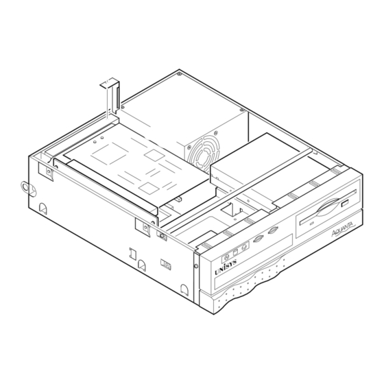
Upgrading Your System Removing and Replacing the System Unit Cover To remove the system unit cover, complete the following steps: Turn the system off. Disconnect the power cord and all peripherals. Place the system unit, with the back panel facing you, on a stable, static-free work surface. - Page 17 Upgrading Your System Figure 1–1. Removing and Replacing the System Unit Cover B1801_01 3814 9779-000 1–5...
-
Page 18: Removing And Replacing The Front Panel
Upgrading Your System Removing and Replacing the Front Panel To remove the front panel: Turn the system off. Disconnect the power cord and all peripherals. Remove the system unit cover, as described earlier in this section Remove the power and drive cables from each drive. Remove the four screws that attach the front panel to the chassis. -
Page 19: Upgrading The Processor
166 or 200 MHz. When you ordered your system, you specified the speed and model of your processor. If you want to upgrade to a faster processor, contact your Unisys Sales Representative for processor availability. To upgrade your processor, complete the following steps. -
Page 20: Removing The Old Processor
Upgrading Your System Removing the Old Processor The CPU is attached to the motherboard by a SAZ (screwdriver actuated ZIF) socket. A heat sink is attached to the top of the CPU with latch bands. Refer to Figure 1–3 for details. -
Page 21: Installing A Processor Chip
Upgrading Your System Figure 1–3. Installing a Processor Chip Heat Sink Socket Insert Screwdriver 200% from scale B1801_03 3814 9779-000 1–9... -
Page 22: Installing The New Processor
Upgrading Your System Installing the New Processor Remove the new processor chip from its packaging. Orient the chip as shown in Figure 1–3, aligning the beveled (cut-off) corner of the chip to the corner of the socket that does not have a pin hole. Press down firmly but gently on the top of the chip until it is fully seated. -
Page 23: Dram Memory
Upgrading Your System Figure 1–4. Sample System Configuration Screen Phoenix BIOS Setup Utility CPU Type : Pentium System ROM : F240-FFFF CPU Speed : 200 BIOS Date : 06/13/97 System Memory : 640 KB Bank 0 SIMM : Fast Page Extended Memory : 31744 KB Display Type: EGA\VGA PS/2 Mouse : Installed... -
Page 24: Upgrading Dram Memory
Since the SIMMs sockets on your motherboard are tin-plated, use only tin- plated SIMMs when upgrading your system memory. If you use gold- plated SIMMs, your system may become unstable. To plan your SIMM configuration, refer to Table 1–1. Contact your Unisys Sales Representative for the availability of SIMMs. Note: If a 36-bit SIMM is installed, use the “ECC/Parity Config”... -
Page 25: Removing Simms
Upgrading Your System Removing SIMMs To remove a preinstalled SIMM, complete the following steps: Turn the system off. Disconnect the power cord and all peripherals. Remove the system unit cover, as described earlier in this section. Remove the front panel, as described earlier in this section. Locate the SIMM retaining clips. -
Page 26: Installing Simms
Upgrading Your System Installing SIMMs Open the first memory upgrade kit and take out the SIMM. Position the SIMM at a 45° angle to the motherboard, as shown in Figure 1–5. Note: SIMMs are keyed and will not seat fully if they are not correctly oriented. Push the SIMM down into the socket, then rock it toward the motherboard. -
Page 27: Upgrading Video Memory
Upgrading Your System Upgrading Video Memory Your system comes with an S3 64V+, PCI Video Controller built into the motherboard. The EDO video has 1MB of DRAM installed by default, and you can add another 1MB. Refer to Figure 1–6. Figure 1–6. -
Page 28: Pipeline-Burst Cache Memory
Upgrading Your System Pipeline-Burst Cache Memory Cache memory enhances system performance. Your system is equipped with 256KB of cache on the motherboard. Adding Feature Boards Your system provides a riser card that supports either two PCI feature boards, or one PCI feature board and one ISA feature board. -
Page 29: Installing Feature Boards
Upgrading Your System Installing Feature Boards To install a feature board, complete the following steps: Turn the system off. Disconnect the power cord and all peripherals. Remove the system unit cover, as described earlier in this section. Remove the screw that secures the slot bracket to the chassis (shown in Figure 1– 7). -
Page 30: Installing A Feature Board
Upgrading Your System 10. Replace the system unit cover, as described earlier in this section. Caution Do not run your system without either a feature board or slot cover in each of the expansion slots. If you operate the system without these items in place, your workstation can generate electromagnetic interference. -
Page 31: Adding Drives
Upgrading Your System Adding Drives Your system unit supports up to three drives: a 3.5-inch, 1.44MB (3-mode) floppy drive; a 3.5-inch, one-third height, internal hard drive; and a “slim ” CD -ROM drive with a 56-pin ATAPI cable. Installing a CD-ROM Drive Turn the system off. -
Page 32: Installing A Cd-Rom Drive
Upgrading Your System 11. Replace the system unit cover, as described earlier in this section, then turn the system on. 12. Run the BIOS Setup utility, and verify the success of your installation. Refer to Section 2 for details. Figure 1–8. Installing a CD-ROM Drive B1801_08 1–20 3814 9779-000... -
Page 33: Upgrading Your 3.5-Inch Hard Drive
Upgrading Your System Upgrading Your 3.5-Inch Hard Drive Turn the system off. Disconnect the power cord and all peripherals. Remove the system unit cover, as described earlier in this section. Remove the front panel, as described earlier in this section. Remove the four screws that secure the old hard drive to the drive bracket, and slide the old hard drive out of the bracket. -
Page 34: Installing A 3.5-Inch Hard Drive
Upgrading Your System Figure 1–9. Installing a 3.5-Inch Hard Drive B1801_09 1–22 3814 9779-000... -
Page 35: Connecting Peripherals To The System Unit
Upgrading Your System Connecting Peripherals to the System Unit Connections for all of your workstation peripherals are located on the back panel of the system unit. See Figure 1–10 for details. Figure 1–10. System Unit Back Panel Power On/Off AC In AC Out Line-Out Line-In... -
Page 36: Where To Go From Here
Upgrading Your System Where to Go From Here After completing a hardware upgrade, it is necessary to run the BIOS Setup utility, as described in Section 2. If you encounter any problems after upgrading the hardware and running the BIOS Setup utility, see Section 3 for information on troubleshooting. -
Page 37: Configuring Your System
Section 2 Configuring Your System This section discusses the BIOS Setup utility, your preloaded software, and how to install additional software. BIOS Setup Utility The BIOS Setup utility is a menu-driven program. Use it to define system parameters and allocate system resources. It is stored in nonvolatile memory and is a permanent part of your system. -
Page 38: Starting The Bios Setup Utility
Starting the BIOS Setup Utility To start the BIOS Setup utility: Turn on your system. When the UNISYS logo screen appears, press . The BIOS Setup main menu appears, as shown in Figure 2–1. Figure 2–1. BIOS Setup – Main Menu PhoenixBIOS Setup - Copyright 1985-95 Phoenix Technologies Ltd. -
Page 39: Changing The Bios Settings
Configuring Your System Changing the BIOS Settings Press the right or left arrow key to highlight the name of the menu you want to activate. When you highlight a menu name, it’s parameters appear on the screen. Press the down or up arrow key to highlight the parameter you want to change. Press the plus or minus key to change the value of the parameter. -
Page 40: Installing Additional Software
Configuring Your System Installing Additional Software Installing Application Software Application software includes commercial, off-the-shelf software packages that perform a variety of functions. To load additional application software, follow the instructions that came with that software. These packages usually include an automated device driver installation program. -
Page 41: Troubleshooting
Section 3 Troubleshooting This section discusses problems you may experience during hardware installation, and possible solutions. If your system experiences a failure not described in this section, you may need to place a service call. This section reviews the following subjects: •... -
Page 42: What To Do When A Bios Password Is Forgotten
Troubleshooting What to Do When a BIOS Password is Forgotten If a BIOS password is forgotten, authorized personnel may use the following procedure to clear the current password from the BIOS. Turn off the system power. Remove the system unit cover, as described in Section 1 in “Removing and Replacing the System Unit Cover.”... - Page 43 Troubleshooting The system begins the Power On Self Test (POST). This test verifies that the system memory, system board, video controller, floppy disk drive, hard disk drive, drive controllers, and peripheral devices are all operational. The system emits one short beep to indicate that it has passed the POST. Note: If the POST detects an error, it displays an error message on the monitor.
-
Page 44: Solving Workstation Problems
Troubleshooting Solving Workstation Problems Your system is designed for simple, trouble-free installation and maintenance. As a rule, your first attempt to power up your equipment will be successful. However, new systems sometimes have easily remedied problems. As mentioned, your system follows a specific routine each time you turn it on. Variations from this routine indicate that your equipment may have a failure. -
Page 45: Troubleshooting An Installation Problem
Troubleshooting • Is the CPU securely connected to the motherboard? • Are the values listed in the BIOS Setup utility correct? For more on the BIOS Setup utility, see Section 2. • If you have a problem booting your operating system, see the manuals that came with your software package for installation instructions. - Page 46 Note: If the system only issues a beep code, or the message does not tell you enough to isolate the problem, contact your Unisys Customer Service Engineer. If you isolate the problem to a specific device, repair or replace the device in question.
-
Page 47: Common Problems
“Troubleshooting an Installation Problem,” earlier in this section. If you still cannot correct the problem, contact your Unisys Customer Service Engineer for help. Note: Faulty devices can cause problems that are difficult to isolate. An effective approach is to replace each suspected device with a known good device, one at a time, and retest the system. - Page 48 Check the system unit fan. If the fan is rotating and the not light. system is running normally otherwise, the Power LED may be defective. Contact your Unisys Customer Service Engineer for help. If the system is not running normally, make sure the power outlet is live.
- Page 49 Troubleshooting Continued 3814 9779–000 3–9...
- Page 50 Troubleshooting Table 3–1. Troubleshooting Guide (cont.) Problem Solution The characters on my monitor Check the monitor interface cable to make sure neither end screen are distorted. has been accidentally pulled free. Make sure the monitor interface cable is not damaged. Use the monitor screen controls to adjust the screen values.
- Page 51 Check the system unit fan. If the fan is rotating and the code when I turn it on. system is running normally otherwise, the speaker may be defective. Contact your Unisys Customer Service Engineer for help. With the power off, remove all feature boards and disconnect all internal drives.
- Page 52 Troubleshooting Continued 3–12 3814 9779–000...
- Page 53 Troubleshooting Table 3–1. Troubleshooting Guide (cont.) Problem Solution My workstation cannot see the Make sure all network cables are properly connected and network. the NIC jumper settings are correct. Verify that the proper driver(s) is installed. My operating system does not Make sure all power cables and drive cables are properly load from the hard disk.
- Page 54 Troubleshooting My system and software had been If the problem occurs when you run a program from a floppy running correctly, but suddenly disk, try a different copy of the program. failed. If the problem is intermittent, check all cable connections and SIMMs.
-
Page 55: Components You Can Replace
Drive interface cables Some of the components in your system are not customer-replaceable. If you isolate a hardware failure to one of these components, call your Unisys Customer Support Center for assistance. Here is a list of components that are not customer-replaceable: •... -
Page 56: Post Beep Codes And Error Messages
Try another power cord. Try another monitor. Try another video card. If that still doesn’t solve the problem, call your Unisys Customer Service Engineer. Beep Code 2 consists of a single long beep that repeats itself. It indicates that a DRAM error has occurred. -
Page 57: Post Messages
Troubleshooting POST Messages If the BIOS detects an error during the POST, one of the following messages will be displayed in a box in the middle of the screen, and the message PRESS F1 TO CONTINUE, DEL TO ENTER SETUP appears in the information box at the bottom. Table 3–2. -
Page 58: Appendix A System Specifications
Appendix A System Specifications Processor Your system uses an Intel Pentium processor. The motherboard supports Pentium P54C 75, 90, 100, 120, 133, 150, 166, and 200 MHz processors and Pentium MMX 166 and 200 MHz processors. The processors are PGA and they plug into a 321-pin PGA ZIF socket. -
Page 59: System Board Memory
System Specifications System Board Memory • All memory resides on the system board using industry standard 72-pin SIMM technology. • SIMMs are 60ns, with tin-lead connectors. You can use either EDO SIMMs or Fast Page SIMMs with parity and ECC mode enabled. •... -
Page 60: Second Level Cache
Your system comes with a Phoenix BIOS, version 4.06, which is IBM compatible and supports Intel’s Pentium processor. The BIOS is implemented on the motherboard through 2Mb of flash EPROM. You can upgrade the BIOS. Contact your Unisys Sales Representative for the availability of a newer BIOS version. -
Page 61: Two-Level Password Security
System Specifications Two-Level Password Security The Supervisor password controls access to the CMOS settings. The User password controls access to the workstation. If both passwords are set, you need the User password to access the workstation, and the Supervisor password to access the CMOS settings. -
Page 62: Cd-Rom Bootable
(see the Boot menu in the BIOS Setup), and the CD must contain a bootable operating system. System Board Jumper Settings The system board jumper settings are all listed on the Aquanta CP Series Configuration Label (CWP 50021), which is attached to the bottom of the motherboard. - Page 63 System Specifications Table A–2. System I/O Address Map (cont.) Address (hex) Size Description 00F0 1 byte Math Coprocessor clear busy latch 00F1 1 byte Math Coprocessor reset 00F2-00FF 14 bytes Math Coprocessor 0120-013F 32 bytes REALTEK LAN Controller Register 0140-0147 8 bytes Crystal Audio System Control Register 0170 - 0177...
-
Page 64: System Memory Map
System Specifications Table A–2. System I/O Address Map (cont.) Address (hex) Size Description 04D0 1 byte INT 1 edge/level control 04D1 1 byte INT 2 edge/level control 0534 - 0537 4 bytes Crystal Audio System CODEC LPT + 400 8 bytes ECP Port 0CF8 - 0CFB 4 bytes... -
Page 65: Keyboard Interface
An IBM PS/2 compatible mouse interface with a 6-pin, mini-DIN, female connector is provided on the back of the unit. The mini-DIN cable is connected to the motherboard. The interface supports the Unisys PS/2 style mouse. It does not support Novell UPS. Table A–5. Mouse Parameters... -
Page 66: Parallel Port Interface
System Specifications Parallel Port Interface The SMC FDC37C935 Super I/O Controller supports the parallel port. One Centronics compatible parallel interface is provided with a 25-pin, D-type, female connector. Also, ECP (Enhanced Compatibility Port) and EPP multi-mode bi-directional parallel port functions are supported. Table A–6. -
Page 67: Serial Port Interfaces
System Specifications Table A–6. Parallel Port Parameters (cont.) Signal Signal (SPP,ECP) Direction EPP Mode Direction Mode Serial Port Interfaces The SMC FDC37C935 Super I/O Controller also supports the serial ports. Two serial port interfaces are provided, each with a 9-pin, D-type, male connector. These are NS161450/PC16550-Compatible UARTS with a send/receive FIFO buffer of 16 bytes. -
Page 68: Sound Controller (Optional
System Specifications Sound Controller (Optional) The Crystal CS4237B is a single chip multimedia audio system controller and codec that provides compatibility with ISA Plug and Play, the Microsoft Windows Sound System, and will run software written for the Sound Blaster and Sound Blaster Pro Interfaces. - Page 69 System Specifications The MIDI/game port has a 15-pin, D-type, female connector. The pin assignments for the MIDI/joystick port are shown in the following table. Table A–8. MIDI/Game Port Parameters Signal In/Output BUTTON 0 Input POSITION 0 Input POSITION 1 Input BUTTON 1 Input BUTTON 2...
-
Page 70: Usb Interfaces
System Specifications USB Interfaces The Universal Serial Bus (USB) is expected to become the standard for low and medium speed peripheral connections. Its flexible architecture, 12 MBs speed with a 1.5 MBs sub-channel, and Plug and Play features, support 127 different physical devices, including the USB Keyboard, USB Mouse, USB Monitor, USB Digital Camera and USB CTI (Computer-Telephony Integration). -
Page 71: Power Led, Power Switch, Hard Disk Drive Led
System Specifications Power LED, Power Switch, Hard Disk Drive One 6-pin header is provided on the motherboard for the front panel indicators. The pin definitions are shown in the following table. Table A–10. Header CN21 Parameters Description Ground Reset Power LED IDE device LED LAN LED or Suspend Mode LED Suspend Mode switch... -
Page 72: Interrupts
System Specifications Interrupts Two interrupt controllers are provided by the Intel PIIX3 PCI chipset. Sixteen interrupts are provided as follows: Table A–12. Interrupt Functions IRQ No Function Interval Timer Keyboard Cascade Interrupt from PIC Serial Port 2 Serial Port 1 Available Floppy Drive Parallel Port... -
Page 73: Counter/Timer
System Specifications Counter/Timer There is a counter/timer in the Intel PIIX3 PCI chipset which contains three independent counters. All three counters are driven from a 14.318 MHz oscillator through a divide-by-12 counter. The output of Counter 0 is connected to the interrupt controller. - Page 74 System Specifications Floppy Disk Drives A floppy cable supports one built-in 3.5" 3-Mode floppy disk drive. A 34 pin header is available on the motherboard for connecting the floppy drive. Table A–14. Floppy Port Parameters Description In/Output -RED_WR Output DRATEO Output -INDEX# Input...
-
Page 75: Ide Hard Disk And Cd-Rom Interface Configuration
System Specifications IDE Hard Disk and CD-ROM Interface Configuration The VT82C586A controller supports an IDE transfer rate of up to 22MB/second to cover PIO mode 4 and Multi-word DMA mode 2 drivers and beyond. There are two IDE headers on the board, one primary and one secondary. IDE 1 is the primary connector which support the 32-bit Local Bus IDE interface, and IDE 2 is the secondary connector which supports the CD-ROM drive. - Page 76 System Specifications Table A–15. IDE Parameters (cont.) Descrption In/Output DDRQ0 Output -DIOW Output -DIOR Output IODRY Input PULL-UP -DDAK0 Input HD_IRQ1* Input Output Output Output -CS1P Output -CS3P Output Input 3814 9779–000 A–19...
-
Page 77: Video Subsystem
System Specifications Video Subsystem The onboard S3 Trio64 + PCI Video Controller comes with two 32x32 EDO 1MB Video Memory chips installed. You can upgrade to two 32x32 EDO 2MB Video Memory chips. Video Pin Assignments The pin assignments for the for the VGA, 15 pin, micro D-type, female video connector are shown in the following table. -
Page 78: Power Supply Assembly
System Specifications Power Supply Assembly The power supply assembly provides 80 watts of DC power. The DC output is sufficient to power the system board, three internal mass storage devices, the optional sound module, and up to two PC-AT/PCI compatible expansion boards. Power is distributed from the power supply through one twelve-pin connector cable to the system board. -
Page 79: On/Off Switch
System Specifications Table A–18. CN1 Power Supply Parameters Description In/Output PG -(Power-good) Input Input +12V Input -12V Input Input Input Input Input On/Off Switch The power On/Off switch is located on the left side of the back panel. System cooling is accomplished by one ball bearing fan that is located inside the power supply assembly. -
Page 80: Suspend Button
System Specifications Suspend Button The suspend button is located on the front panel. Press it to enter the suspend mode. If the system is in the suspend mode, press it to restore the system to full power mode. Speaker The mother board contains a built-in mini-speaker. Dimensions The dimensions and weight of your system are shown in the following table. -
Page 81: Maximum Size For Add-On Cards
System Specifications Maximum Size for Add-On Cards Your system supports ISA cards and PCI cards of the following dimensions: ISA CARDS: Length—190.5mm/7.5in. Width—101.6mm/4.0in. PCI CARDS: Slot 1: Length—144.8mm/5.7in. (w/CD-ROM) Length—190.5mm/7.5in. (w/o CD-ROM) Width—101.6mm/4.0in. Slot 2: Length—134.6mm/5.3in. Width—85.1mm/3.35in. Note: BNC connectors on feature boards may cause installation problems Supported Operating Systems MS-DOS 6.22 Microsoft MS-DOS version 6.22 is supported... -
Page 82: Sco Unix
System Specifications OS/2 IBM OS/2 operating system, version 2.1 and Microsoft Presentation Manager services are supported. The system is certified by the OS/2 certification program. SCO UNIX SCO UNIX version 3.2.4.2, SCO Open Desktop 3.0.0, and SCO OpenServer Release 5.0 (IDE or SCSI CD-ROM required) are supported. The system is certified by the SCO UNIX certification program. -
Page 83: Operating Environment
System Specifications Operating Environment The following are the conditions under which you can turn on and operate your system without damage to any of its components. Exceeding these parameters may cause damage to your system. Table A–20. Operating Environment Description Range Temperature +55.4°... -
Page 84: Shipping Specifications
System Specifications Shipping Specifications The following are conditions under which your system will not sustain damage, as long as it is properly packaged for shipping. These shipping specifications assume that you repack your equipment in its original container and use the original shipping material. Exceeding these parameters may cause damage to your system. - Page 86 Index CMOS configuration, 3-4 component 3.5-inch internal-access drive screws, 1-2 installing, 1-21 connecting cables, 1-23 connectors protecting, 1-2 conventions used in the manual, xii ac power connector, 1-23 cover adding drives, 1-19 removing, 1-4 audience, xi replacing, 1-4 installation, 1-10 customer-replaceable components, 3-12 BIOS main screen, 2-2...
- Page 87 Index POST, 3-3 beep codes, 3-13 installation messages, 3-14 cache memory, 1-16 Power LED, 3-8 CPU, 1-10 Power On Self Test messages, 3-14 feature boards, 1-16 processor, 1-7 preliminary notes, 1-2 preloaded software, 2-3, 2-4 SIMMs, 1-12, 1-14 system memory, 1-12 processor troubleshooting, 3-5 installation, 1-7...
- Page 88 Index troubleshooting applications, 3-11 boot problems, 3-10 cluster problems, 3-11 common problems, 3-7 disk drive problems, 3-10, 3-11 general discussion, 3-4 installation problems, 3-5 keyboard problems, 3-9 monitor problems, 3-8 mouse problems, 3-10 operating system problems, 3-11 power problems, 3-7 upgrading cache memory, 1-16 DRAM, 1-12...
Need help?
Do you have a question about the Aquanta CP Series and is the answer not in the manual?
Questions and answers