Advertisement
Table of Contents
88 5588 941
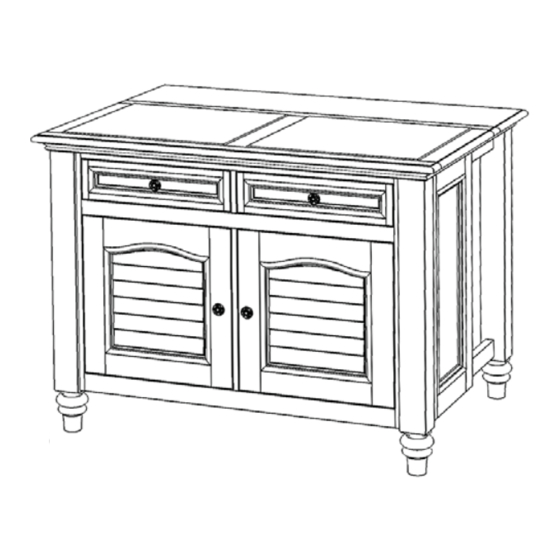
Bermuda
Kitchen Island
IMPORTANT NOTE
Carefully remove all the parts from the carton and put
them individually on a soft cloth to prevent scratches
or other damages occuring to the wood parts.
We have taken great care in the design of this
product and request that you carefully and strictly
follow our assembly instructions to ensure a
completed product as it was designed.
Part List
A1.
Top
1 pc.
A2.
Leaf Top
1 pc.
For assembly see instructions in carton 88 5588-942
Home Styles Consumer Assistance: www.homestyles-furniture.com,
servicedesk@homestyles-furniture.com, 888-680-7460, 877-831-0319
Advertisement
Table of Contents

Subscribe to Our Youtube Channel
Related Manuals for Home Styles Bermuda 88 5588 941


Summary of Contents for Home Styles Bermuda 88 5588 941
- Page 1 Part List 1 pc. Leaf Top 1 pc. For assembly see instructions in carton 88 5588-942 Home Styles Consumer Assistance: www.homestyles-furniture.com, servicedesk@homestyles-furniture.com, 888-680-7460, 877-831-0319...
-
Page 2: Part List
88 5588 943 Bermuda Kitchen Island Carton quatity: 1 Side Frame Side Frame 1 pc. 1 pc. Leaf Top 1 pc. 1 pc. Tools required for assembly : Phillips screwdriver Tools recommended for assembly : Leve Home Styles Consumer Assistance: www.homestyles-furniture.com, servicedesk@homestyles-furniture.com, 888-680-7460, 877-831-0319... -
Page 3: Important Note
Part List Side Frame Side Frame 1 pc. 1 pc. For assembly see instructions in carton 88 5588-942 Home Styles Consumer Assistance: www.homestyles-furniture.com, servicedesk@homestyles-furniture.com, 888-680-7460, 877-831-0319... -
Page 4: Assembly Instruction
Assembly Instruction 2 / 7 IMPORTANT * Do not tighten up all the screws until each part is properly assembled. * You should keep Hex Wrench in a safe place as you may need to tighten up the Head Cap Bolts in the future. * Use a soft cloth between these parts and the fl... - Page 5 Assembly Instruction 3 / 7 STEP 3 Attach Front Rail (I), (J), Bottom (B) and Back Rail (K) to Middle Panel (D) using Cam Locks. (see Figure 2) Attach Back Piece (M) and Back Rail (L) to unit using Cam Locks. Slide Back Panel (N) into the grooves in Back Rail (K), (L) and Back Piece (M).
- Page 6 Assembly Instruction 4 / 7 Machine Screw Hinge Wood Screw for Hinge Pull Handle STEP 6 EP 6 Attach Hinges, Pull Handles to Doors (F), (G) with Wood Screws and Machine Screws into the pre-drilled holes. (see Figure 4), (see Figure 5) Figure 4 Figure 5 Figure 6...
- Page 7 Assembly Instruction 5 / 7 Wood Dowel Wood Dowel Flat Washer Spring Washer Head Cap Bolt Wood Screw for Hinge Adjustable Pin STEP 8 Insert Wood Dowels into the unit. Place top unit onto unit and attach with Flat Washers, Spring Washers and Head Cap Bolts. (see Figure 7) Attach Door (F), (G) to unit with Wood Screws for Hinge into the pre-drilled holes.
- Page 8 Assembly Instruction 6 / 7 TOP EXTENSION INSTRUCTIONS STEP 1 Lift up the Leaf Top. STEP 2 Holding the Leaf Top up, pull out a back leg from the unit; then pull out the other back leg. Note : Unit must be level in order for the back legs to be pulled out.
- Page 9 Assembly Instruction 7 / 7 Drawer (Q) Figure 1 STEP 1 Attach Q1 to Q2 and Q4, using MAKE SURE ROLLER a Phillips screwdriver and IS ON THE BACK long wood screws (4X), tighten halfway. Attach Q2 to Q3 and Q4 using Figure 2 Figure 2 long wood screws (4X), tighten...
Need help?
Do you have a question about the Bermuda 88 5588 941 and is the answer not in the manual?
Questions and answers