Table of Contents
Advertisement
Quick Links
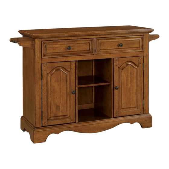
88 5538 952
Large Kitchen Cart
(Oak Finish)
IMPORTANT NOTE
Carefully remove all the parts from the carton and put
them individually on a soft cloth to prevent scratches
or other damages occuring to the wood parts.
We have taken great care in the design of this
product and request that you carefully and strictly
follow our assembly instructions to ensure a
completed product as it was designed.
PART LIST (in this carton)
A.
Top
.
1 pc
B.
Base
.
1 pc
J.
Front Rail
.
1 pc
K.
Front Rail
.
1 pc
L.
M.
Door
Door
.
.
1 pc
1 pc
HARDWARE LIST
Caster
two lock
two non-lock
4 pcs.
Tools Required For Assembly : Phillips screwdriver
Casual Attire For Today's Home
C.
Side Panel
.
1 pc
N.
Back Panel
O.
Back Piece
.
2 pcs
.
2 pcs
Hex Wrench
Head Cap Bolt
1 pc.
8 pcs. (+1 extra)
Small
Adjustable Pin
Hex Wrench
16 pcs. (+1 extra)
1 pc.
E.
Middle Panel
.
1 pc
D.
Side Panel
Q.
.
Back Rail
1 pc
.
1 pc
R.
Back Rail
.
1 pc
U.
Towel Bar
S.
2 pcs
Arm
.
2 pcs
P.
T.
Arm
Back Panel
.
.
2 pcs
1 pc
Cam Lock Screw
20 pcs. (+1 extra)
Wood Screw
Wood Screw
for Drawer (Short)
for Caster
16 pcs. (+1 extra)
12 pcs. (+1 extra)
G.
Divider
.
1 pc
H.
Shelf
.
2 pcs
I.
F.
Shelf
Middle Panel
.
2 pcs
.
1 pc
V.
.
Drawer
.
2 pcs
(Drawers require assembly.
Please refer to the last page
of these assembly instructions.)
Machine Screw
Cam Lock
4 pcs.
20 pcs. (+1 extra)
Wood Screw
for Drawer (Long)
Pull Handle
16 pcs. (+1 extra)
4 pcs.
Advertisement
Table of Contents

Subscribe to Our Youtube Channel
Related Manuals for Home Styles 88 5538 952


Summary of Contents for Home Styles 88 5538 952
- Page 1 88 5538 952 Large Kitchen Cart (Oak Finish) IMPORTANT NOTE Carefully remove all the parts from the carton and put them individually on a soft cloth to prevent scratches or other damages occuring to the wood parts. We have taken great care in the design of this...
- Page 2 Assembly Instructions 2/6 IMPORTANT Do not tighten up all the screws until each part is properly assembled. You should keep Hex Wrench in a safe place as you may need to tighten the Head Cap Bolts in the future. Cam Lock Screw STEP 1 Insert Cam Lock Screws into the pre-drilled holes of Side Panel (C),(D) and Top (A)
- Page 3 Assembly Instructions 3/6 Cam Lock STEP 3 Attach Back Rail (G) to Side Panel (C) with Cam Lock. Attach Back Piece (O) to Back Rail (G) and slide Back Panel (N) , (P) into place. Attach Back Rail (Q) to the unit with Cam Lock. (see Figure 2) Cam Lock Figure 2 STEP 4...
- Page 4 Assembly Instructions 4/6 Cam Lock STEP 5 Attach Side Panel (D) to unit with Cam Locks. Cam Lock STEP 6 Attach Base (B) to unit with Cam Locks.
- Page 5 Assembly Instructions 5/6 Cam Lock Figure 3 STEP 7 Attach Arms (S) to unit with Head Cap Bolts. (see Figure 3) Head Cap Bolt Attach Towel Bars (U) to pre-drilled hole of Arm (S). Attach Arms (T) to unit with Head Cap Bolts.
- Page 6 Assembly Instructions 6/6 Drawer (V) Figure 1 STEP 1 Attach V1 to V3 and V4, using a Phillips screwdriver and Figure 2 long wood screws (4X), MAKE SURE ROLLER tighten halfway. IS ON THE BACK Attach V2 to V3 and V4 using long wood screws (4X), tighten halfway.
Need help?
Do you have a question about the 88 5538 952 and is the answer not in the manual?
Questions and answers