
Related Manuals for Banner DXMR90-X1 Series


Summary of Contents for Banner DXMR90-X1 Series
- Page 1 DXMR90-X1 Series Controller Instruction Manual © Banner Engineering Corp. May 09, 2023 www.bannerengineering.com...
-
Page 2: Table Of Contents
Contents Chapter 1 Overview of the DXMR90-X1 DXMR90-X1 Models..................................... 6 Hardware Overview ..................................... 7 Automation Procotols ....................................7 Modbus Overview ......................................8 Modbus Registers ......................................8 Dimensions ........................................9 Chapter 2 Quick Start Guide Apply Power to the Controller..................................11 Wiring........................................11 Configuration Instructions................................... 12 DXM Configuration Software ................................ - Page 3 Industry Canada Statement for Intentional Radiators ......................... 50 File System and Archive Process ................................50 Update Your DXM Processor Firmware Using the Configuration Software ....................50 DXM Support Policy ....................................51 Firmware Updates ....................................51 Website Information .................................... 51 Feature Requests ....................................51 Potential DXM Issues ..................................51 DXM Security ...................................... 52 Warnings........................................52 Banner Engineering Corp Limited Warranty ............................53 Contact Us ......................................53 Document Information ..................................54 ...
- Page 4 Blank page ...
-
Page 5: Chapter 1 Overview Of The Dxmr90-X1
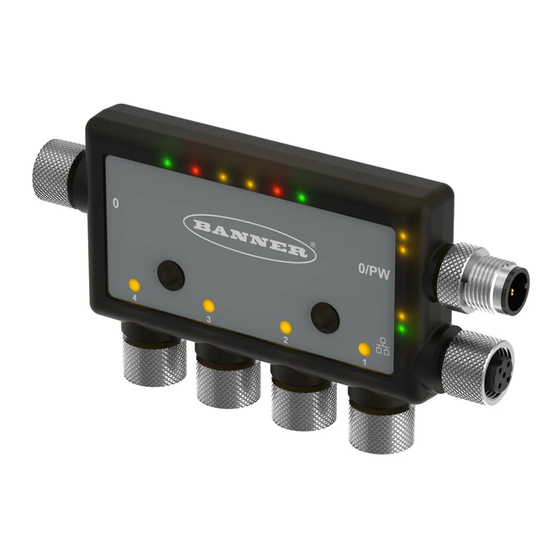
DXMR90-X1 Series Controller Instruction Manual DXMR90-X1 Models......................................6 Hardware Overview ......................................7 Automation Procotols ......................................7 Modbus Overview ....................................... 8 Modbus Registers ......................................8 Dimensions ......................................... 9 Chapter 1 Overview of the DXMR90-X1 Banner's DXMR90-X1 Series Controller consolidates data from multiple sources to provide local data processing as well as accessibility for host systems as a platform for the Industrial Internet of Things (IIoT). The DXMR90-X1 contains four individual Modbus masters allowing for concurrent communication to up to four independent networks. Data is collected into the internal logic controller to facilitate edge processing, protocol conversion to Industrial Eth- ernet, and pushing information to web servers. Overview of the DXMR90-X1 Series Controller Configurable Modbus Port 0... -
Page 6: Dxmr90-X1 Models
DXMR90-X1 Series Controller Instruction Manual Logic Controller Program the DXMR90-X1's logic controller using action rules and/or ScriptBasic or MicroPython programming lan- guages, which can execute concurrently. The control functions allow freedom when creating custom sensing and control sequences. The logic controller supports the Modbus protocol standards for data management, ensuring seamless inte- gration with existing automation systems. File password protection is an option. Action Rules • Thresholds (IF/THEN/ELSE) with timers, minimum on/off time • Math/Logic Rules (arithmetic and bitwise operators) • Control Logic (logical operators and SR/T/D/JK flip flops) • Trending (multiple averaging filters) • Tracking (counts, on/off times) • Email notifications ... -
Page 7: Hardware Overview
DXMR90-X1 Series Controller Instruction Manual Hardware Overview The DXMR90-X1 Series Controller can have multiple configurations. The DXMR90-X1 will have a model number label on the housing. Use the model number to identify which boards are included in the controller. Automation Procotols The DXMR90-X1 Series Controller supports the following automation protocols. EtherNet/IP™ By default, EtherNet/IP is disabled. Configure the DXMR90-X1 Local Registers as EtherNet/IP input or output registers using the DXM Configuration Software. A single register can only be set as either an EtherNet/IP input or output register. EtherNet/IP registers are limited to 228 registers set as E/IP Originator to DXM and 228 registers set as DXM to Origina- tor Modbus® RTU The DXMR90-X1 manages five separate physical ports running the Modbus RTU protocol. The DXMR90-X1 is the Mod- bus Master when operating the Modbus master RTU port (port 1–4). The DXMR90-X1 uses the master Modbus RTU bus to communicate with locally connected Modbus slave devices. The other Modbus RTU port (port 0) is used by a host system to access the DXMR90-X1 as a slave device. The slave Modbus RTU port allows access all the internal local registers concurrently with the master RTU port. Port 0 can be con- figured as a Modbus Master Port using the DXM Configuration Software but is defined as a slave port by default. Configure the port parameters using the DXM Configuration Software. Modbus TCP/IP A host system acting as a Modbus master (client) can access the DXMR90-X1 using the Modbus TCP/IP protocol over Ethernet. Standard Modbus TCP port 502 is used by the DXMR90-X1 for all Modbus TCP/IP requests. All internal local registers are available to the host system concurrently with Modbus TCP. ... -
Page 8: Modbus Overview
DXMR90-X1 Series Controller Instruction Manual Modbus® is a registered trademark of Schneider Electric USA, Inc. PROFINET® is a registered trademark of PROFIBUS Nutzerorganisation e.V. EtherNet/IP™ is a trademark of ODVA, Inc. All other trademarks and registered trademarks cited are the property of their respective owners. Modbus Overview The DXMR90-X1 Series Controller uses internal 32-bit registers to store information. The processor's internal Local Registers serve as the main global pool of registers and are used as the common data exchange mechanism. External Modbus device registers can be read into the Local Registers or written from the local data registers. ... -
Page 9: Dimensions
DXMR90-X1 Series Controller Instruction Manual Continued from page 8 Local Registers Type Description 5001–7000 32-bit integer Local data registers 7001–8000 32-bit non-volatile integer Data flash, non-volatile > 10000 Read-only virtual registers, system-level data Modbus registers for the LCD board (Modbus slave ID 203) Modbus Register LED Color State 2101: bit 0 LED 1 Green 2102 : bit 0 LED 2 Red 2103 : bit 0 LED 3 Amber 1 = On 0 = Off ... - Page 10 Blank page ...
-
Page 11: Chapter 2 Quick Start Guide
DXMR90-X1 Series Controller Instruction Manual Apply Power to the Controller..................................... 11 Configuration Instructions....................................12 Mechanical Installation ..................................... 16 Chapter 2 Quick Start Guide Apply Power to the Controller Follow these instructions to apply 12–30 V DC power to the DXMR90-X1 using a wall plug. Required equipment: • DXMR90-X1 Series Controller • PSW-24-1 Wall plug power supply; 24 V DC, 1 A (or equivalent 24 V DC M12 power supply) Connect the PSW-24-1 power supply to the male M12 connector on the DXMR90-X1, Port 0. Plug in the PSW-24-1 wall plug power supply. Wiring Ports 0-4 female connector Port 0–4 5-pin M12 Connector (female) ... -
Page 12: Configuration Instructions
DXMR90-X1 Series Controller Instruction Manual D-coded industrial Ethernet connector 4-pin Industrial Ethernet Connector (female) Pin Wire Color Description 1 Black (bk) +Tx 2 Red (rd) +Rx 3 Green (gn) –Tx 4 White (wh) –Rx Configuration Instructions DXM Configuration Software Configure the DXMR90-X1 using the configuration software. Use this software to customize your configuration and to process data from the Controller. ... -
Page 13: Configuring The Dxmr90 Controller
DXMR90-X1 Series Controller Instruction Manual IMPORTANT: The DXMR90-X1 Series Controller comes preloaded with a default configuration XML file. You can download the default XML on the product page for the DXMR90-X1. This quick start guide outlines the basic operations to set up a DXMR90-X1 using the configuration software. For a more comprehensive explanation of features, refer to the DXM Configuration Software Instruction Manual (p/n 209933). Configuring the DXMR90 Controller This section will walk you through the method of setting up the DXM Configuration Software and communicating with a con- nected DXM device. Version 4 of the DXM Configuration Software supports multiple DXM device models, each of which in- corporates different features. As soon as a DXM model is connected to your computer, the software automatically detects the correct model and loads the appropriate screens. You may also manually select which model of DXM you are configuring if you intend to create a configu-... - Page 14 DXMR90-X1 Series Controller Instruction Manual The software only loads a file to the DXM. Internal parameter settings that are changed in the tool but not saved to the file will not be sent to the device. Modify Multiple Registers Modify a range of registers from the Local Registers › Local Registers in Use › Modify Multiple Registers screen. ...
- Page 15 DXMR90-X1 Series Controller Instruction Manual Name your rule. Select the Port number to which the device is connected. Select the Modbus ID of the device. Select how many registers to read, and the beginning register. Define the register type, how often to read the register, and any other appropriate parameters. If necessary, select the error condition. For this example, if the read function fails after three attempts, the read rule writes 12345 to the DXM local registers. Notice the list of local register names this read rule is using. Read Rules - Configuration Example Parity Baud Rate Defined for both the Modbus master and slave ...
-
Page 16: Set The Ip Address
DXMR90-X1 Series Controller Instruction Manual Set the IP Address Follow these instructions to change the DXMR90-X1's IP address. By default, the DXMR90-X1 is set to a static IP address of 192.168.0.1. The IP address can be changed by using the DXM Configuration Software and updating the XML. Launch the DXM Configuration Software. Go to the Settings › Ethernet screen. In the IP Address section, select Static IP or DHCP from the drop-down list. ◦ If Static IP is selected, enter the IP address, Subnet, and Gateway address as desired. ◦ If DHCP is selected, the IP address, Subnet, and Gateway address are grayed out and not configurable. Changing the IP Address to DHCP can make it so the DXM cannot be reached. Before changing this to DHCP, you MUST have a server that is going to assign an IP Address to the DXMR90-X1. Save your changes to the configuration file (File › Save). Upload the configuration file to your controller (DXM › Send Configuration to DXM). ... - Page 17 DXMR90-X1 Series Controller Instruction Manual 16.0 mm 3 mm * for minimum engagement of Screw Length = 16.0 mm + “X” mm + 3 mm three threads CAUTION: Do not overtighten the DXMR90-X1's mounting screw during installation. Overtightening can affect the performance of the DXMR90-X1. May 09, 2023 © Banner Engineering Corp.
- Page 18 Blank page ...
-
Page 19: Chapter 3 Controller Connections
DXMR90-X1 Series Controller Instruction Manual Ethernet ..........................................19 Internal Local Registers (Slave ID 199)................................19 Connecting to Remote Modbus Devices ................................22 Chapter 3 Controller Connections Connections for the DXMR90-X1 Configurable Modbus Port 0 (female) Configurable Modbus Port 0 and Power (male) - Page 20 DXMR90-X1 Series Controller Instruction Manual Continued from page 19 Local Registers Type Description 7001–8000 32-bit non-volatile integer Data flash, non-volatile > 10000 Read-only virtual registers, system-level data Local Registers 1–845 and 5001–7000 (Internal Processor Memory, 32-bit, Unsigned)—The Local Registers are the main global pool of registers. Local Registers are used as basic storage registers and as the common data exchange mechanism. External Modbus device registers can be read into the Local Registers or written from the Local Registers. The DXMR90-X1, as a Modbus master device or a Modbus slave device, exchanges data using the Local Registers.
- Page 21 DXMR90-X1 Series Controller Instruction Manual Continued from page 20 Registers Definition 10055–10056 Alarms, smtp, attempts Email attempts 10057–10058 Alarms, smtp, fails Email failures 10100 Number of read maps in default 10101 Number of read map successes 10102 Number of read map timeouts Read Map statistics 10103 Number of read map errors 10104 Read map success streak 10105 Number of write map successes 10106 Number of write map timeouts Write Map statistics 10107 Number of write map errors 10108 Write map success streak 10109 ...
-
Page 22: Connecting To Remote Modbus Devices
DXMR90-X1 Series Controller Instruction Manual Continued from page 21 Register Definition 2x027 Socket x Rule 0 broadcasts 2x029 Reserved 2x031 Socket x Rule 1 transmits 2x033 Socket x Rule 1 receives 2x035 Socket x Rule 1 timeouts 2x037 Socket x Rule 1 broadcasts 2x039 Reserved Reset Codes—The reset codes are in virtual register 11015 and define the condition of the last restart operation. Reset codes Reset Code Definition 0 Undefined 1 Unknown 2 General 3 Brownout ... -
Page 23: Set The Master And Slave Port Parameters
DXMR90-X1 Series Controller Instruction Manual DXM Configuration Software to define the operational settings for both the Modbus RTU master ports 1–4 and the Modbus RTU slave port 0. Set the Master and Slave Port Parameters The basic communications parameters for the RS-485 ports are set in the DXM Configuration Software and are saved in the XML configuration file. Each port can have unique settings such as a unique baud rate, parity, timeout, and delays between messages. ... - Page 24 DXMR90-X1 Series Controller Instruction Manual Slave Port 0 Settings May 09, 2023 © Banner Engineering Corp.
-
Page 25: Assigning Modbus Slave Ids
DXMR90-X1 Series Controller Instruction Manual Assigning Modbus Slave IDs .................................... 25 Modbus Operation ......................................26 Modbus Communication Timeouts ................................... 26 Modbus TCP Client ......................................26 Chapter 4 Working with Modbus Devices The DXMR90-X1 has five physical RS-485 connections using Modbus RTU protocol. The master Modbus RS-485 ports are for the DXMR90-X1 to act as a Modbus master device to control external Modbus slave devices. The Modbus master RS-485 ports are labeled Port 1–4. The Modbus slave port is used when another Modbus master device wants to communicate with the DXMR90-X1 when the DXMR90-X1 is a Modbus slave device. The Modbus slave RS-485 port is labeled Port 0. DXMR90-X1 system overview Processor/Outputs (Base Board) Local Registers Outputs (Modbus ID 203) Processor Controlled... -
Page 26: Modbus Operation
DXMR90-X1 Series Controller Instruction Manual Modbus Operation All Modbus transactions are managed by a central Modbus engine. If there are Modbus messages intended for a Modbus slave that doesn't exist, the Modbus engine waits for a response until the timeout period is expired. This slows down the Modbus polling loop for read and write operations. Each Master port is running its own modbus engine; timeouts on one port will not affect the other ports. ... -
Page 27: Chapter 5 Configuration Instructions
DXMR90-X1 Series Controller Instruction Manual Scheduler .......................................... 27 Authentication Setup ......................................28 Register Flow and Configuration ..................................30 EtherNet/IP™ Configuration....................................31 Set up the Email ........................................ 32 Push Retries........................................35 Chapter 5 Configuration Instructions Scheduler Use the Scheduler screens to create a calendar schedule for local register changes, including defining the days of the week, start time, stop time, and register values. Schedules are stored in the XML configuration file, which is loaded to the DXMR90-X1. Reboot the DXMR90-X1 to activate a new schedule. If power is cycled to the DXMR90-X1 in the middle of a schedule, the DXMR90-X1 looks at all events scheduled that day and ... -
Page 28: Create A One-Time Event
DXMR90-X1 Series Controller Instruction Manual Register updates can be changed up to two times per day for each rule. Each rule can be set for any number of days in the week by clicking the buttons M, T, W, Th, F, S, or Su. If two register changes are defined for a day, define the start time to be before the end time. Select End Value to enable the second event in a 24 hour period. To span across two days (crossing the midnight boundary), set the start value in the first day, without selecting End Value. Use the next day to create the final register state. ... -
Page 29: Set The Controller To Use Authentication
Configuration Software. Click on Send Authentication. The controller must be connected to the PC for this operation to succeed. The data transmits directly to the DXMR90-X1's non-volatile memory. If successful, a pop-up window appears, asking to reboot the device. Select Yes to reboot the device. Set the Web Services to Use Authentication At the Banner Cloud Data Services website, go to Settings › Sites. To edit the site settings, click Edit on the line of the site name. Settings > Sites screen of the Banner CDS website May 09, 2023 © Banner Engineering Corp. -
Page 30: Controller Configuration Authentication
DXMR90-X1 Series Controller Instruction Manual At the bottom of the pop-up window is a checkbox to enable authentication/validation. Enter the same username and password as used in the DXM Configuration Software. The username and password do not need to be a defined user within the Banner Cloud Data Services website. Controller Configuration Authentication The DXMR90-X1 can be programmed to allow changes to the configuration files only with proper authentication by setting up a password on the Settings › Administration screen in the DXM Configuration Software. With the DXMR90-X1 connected to the PC, click Get Device Status. The DXMR90-X1 status displays next to the button. Settings > Administration screen Use the DXM Configuration Software to: • Set the Admin Password • Change the Admin Password • Remove the Admin Password To change or remove an admin password, the current password must be supplied. The DXMR90-X1 must be connected to ... -
Page 31: Troubleshooting A Configuration
Configuration to Device or Download Configura- tion from Device under the Device menu. EtherNet/IP™ Configuration The DXMR90-X1 can be configured to send/receive local register data to and from an EtherNet/IP™ host. EDS (Electronic Data Sheet) files allow users of the EtherNet/IP protocol to easily add a Banner DXM device to the PLC. Download the EDS files from the Banner website. • DXM EDS Configuration File (for PLCs) (p/n b_4205242) •... -
Page 32: Configuring The Controller
DXMR90-X1 Series Controller Instruction Manual Configuring the Controller Use the configuration software to define the Protocol conversion for each local register to be EIP Originator › DXM or EIP DXM › Originator from the Edit Register or Modify Multiple Register screens. Define a DXM local register as EIP Originator › DXM when the host PLC (Originator) will send data to the DXMR90-X1 local register (DXM). Define a DXM local register as EIP DXM › Originator when that register data will be sent from the DXMR90-X1 (DXM) to the host PLC (Originator). Data from an EIP controller in assembly instance 112 is data destined for the DXMR90-X1 local registers. The PLC is normal- ly configured for INT or UINT data transfer. This allows for a seamless transfer of data. EIP Assembly Instance 112 (16-bit) DXM Local Registers Adrs Data Adrs Data 0 1122 1 1122 1 3344 2 3344 2 5566 3 ... -
Page 33: Mail Server Authentication
DXMR90-X1 Series Controller Instruction Manual Mail Server Authentication Complete the mail server settings to have the DXMR90-X1 send email alert messages. The SMTP password is stored in the DXMR90-X1, not the XML configuration file. Use the Settings › Notifications screen to complete this configuration. Mail server settings After selecting Enable SMTP Authentication for the first time, a pop-up box appears with additional instructions to complete the mail server authentication process. After entering the user name and password, click on Send SMTP Password to save the user name and password to the DXMR90-X1. The DXMR90-X1 must be connected to the PC to complete this operation. If successful, a pop-up window appears, asking to reboot the device. Select Yes to reboot the device. Define the Network Interface Settings On the Cloud Services screen, define the network connection settings by selecting HTTP Cloud Push to send data to Banner CDS or AWS IoT Core Push to send data to AWS IoT Core. If you don't require pushing data to a web server, set the Cloud Push interval to zero. May 09, 2023 © Banner Engineering Corp. -
Page 34: Configure Your Ethernet Connection
DXMR90-X1 Series Controller Instruction Manual Cloud Services screen Configure your Ethernet Connection To send email based on a threshold rule, first define the network and email servers. When selecting Ethernet, go to the Set- tings › Ethernet screen. To define the Ethernet IP address, give the DXMR90-X1 a static IP address. In most cases you may select the device to use DHCP and have the IP address automatically assigned. DNS settings are not typically required. The DXMR90-X1 uses a public service to resolve Domain names, but if the network connection does not have Internet access, the DNS settings may be required. Settings > Ethernet screen Set the Email Parameters From the Settings › Notifications screen, enter the SMTP definition, login, and password for a mail server. May 09, 2023 © Banner Engineering Corp. -
Page 35: Define Threshold Rules For Email
DXMR90-X1 Series Controller Instruction Manual To send email, you must supply the SMTP Server, Server Port, and login credentials. The default SMTP port is 25 but may need to be adjusted for Ethernet-based networks. Note that many facilities block port 25. Port 587 is another common SMTP submission port. The SMTP password is not stored in the XML configuration file, but on the DXMR90-X1. After the password is entered, click on Send SMTP Password to send it to the DXMR90-X1. The password is stored in non-volatile memory, so reboot the DXMR90-X1 to recognize the new password. ... - Page 36 DXMR90-X1 Series Controller Instruction Manual Event/Action—Event-based pushes caused by Action rules sent using email follow the same process when failures occur, based on the network connection. Email—There are no retries for emails that fail to be sent from the DXMR90-X1. May 09, 2023 © Banner Engineering Corp.
-
Page 37: Chapter 6 Profinet
DXMR90-X1 Series Controller Instruction Manual General Station Description Markup Language File ............................37 DXM PROFINET IO Data Model ..................................37 Configure the DXM Controller for a PROFINET IO Connection ........................37 Slots and Modules for DXM PROFINET ................................38 Configuration Instructions ....................................12 Chapter 6 PROFINET® PROFINET is a data communications protocol for industrial automation and processes. PROFINET IO defines how con- trollers (IO controllers) and peripheral devices (IO devices) exchange data in real-time. PROFINET® is a registered trade- mark of PROFIBUS Nutzerorganisation e.V. and the standard is maintained by PROFIBUS & PROFINET International (PI) , an organization headquartered in Karlsruhe, Germany. Only the DXMR90, DXM700, DXM1000, and DXM1200 Controller models support PROFINET IO. General Station Description Markup Language File A PROFINET General Station Description (GSD) file is a description of an IO device provided by the device manufacturer in an XML format (GSDML.xml). ... -
Page 38: Slots And Modules For Dxm Profinet
DXMR90-X1 Series Controller Instruction Manual Status indicator bar ◦ If the Application Status indicator is red, close and restart the DXM Configuration Tool, unplug and re-plug in the cable and reconnect the DXM to the software. ◦ If the Application Status indicator is green, the file upload is complete. ◦ If the Application Status indicator is gray and the green status bar is in motion, the file transfer is in progress. After the file transfer is complete, the device reboots and begins running the new configuration. Slots and Modules for DXM PROFINET There are ten slots to accommodate the DXM Controller data. Slots for input and output values Values ... - Page 39 DXMR90-X1 Series Controller Instruction Manual Continued from page 38 Size Module ID Submodule ID Module Register Start Register End Direction (bytes) x506 x507 x051 x055 22 x851 x859 x001 x003 8 x506 x507 0x48 0x01 IO-Link In/Out 4/4 Byte + Status Bidirectional x051 x053 18 ...
-
Page 40: Install The Gsd File
DXMR90-X1 Series Controller Instruction Manual Continued from page 39 Example Configuration Slot Module Description Slot 5 Digital Output Use SIO Output mode on Port 4 Slot 10 ISDU 190 Byte + Status ISDU read/write access for all ports in IO-Link mode Configuration Instructions ... - Page 41 DXMR90-X1 Series Controller Instruction Manual Configure networks screen Click Options and select Manage general station description file (GSD). The Install general station decription file window opens. Click the More options (...) icon to the right of the Source path field and browse to the location the DXM GSD file was downloaded to. Select the DXM GSD file. Click Install. Hardware catalog May 09, 2023 © Banner Engineering Corp.
-
Page 42: Change The Device Ip Address
DXMR90-X1 Series Controller Instruction Manual The system installs the DXM GSD file and places it in the Hardware catalog. In the example, the DXM GSD file is lo- cated under Other field devices › PROFINET IO › Banner Engineering Corp. › Banner. If the DXM GSD file does not install properly, save the log and contact Banner Engineering Corp. Change the Device IP Address Follow these instructions to change the IP address of the DXM device using the Siemens TIA Portal (v14) software. Use these instructions as a basis if you are using another controller (PLC). Launch the Siemens TIA Portal (v14) software. Click Open existing project. ... - Page 43 DXMR90-X1 Series Controller Instruction Manual Online & diagnostics menu and screen The Online & diagnostics windows displays. Select Assign IP address under Functions. Click Accessible devices. The Select device window searches the network for available devices. Determine the device to be adjusted via the MAC address and select it. Click Apply. The IP address for the device is updated. Click Assign IP address to complete the step. This step is completed for every device. By default, each DXM shipped from the factory is assigned the IP address 192.168.0.1. Immediately after the PROFINET protocol is enabled, the DXM has an IP address of 0.0.0.0. We recommend using the TIA Portal to give the DXM an IP address so that the address is saved in the unit.
-
Page 44: Change The Device Name
DXMR90-X1 Series Controller Instruction Manual Change the Device Name Follow these instructions to change the name of the DXM using the Siemens TIA Portal (v14) software. Use these instruc- tions as a basis if you are using another controller (PLC). Open a project and click on Devices & networks. The Network view displays. Right-click on the DXM icon and select Assign device name. The Assign PROFINET device name window displays. The software searches for devices of the same type. Enter the desired name in the PROFINET device name field. Note that each name can be used only once. Click Assign name. The device now has a PROFINET name. May 09, 2023 © Banner Engineering Corp. -
Page 45: Chapter 7 Accessories For The Dxmr90-X1
DXMR90-X1 Series Controller Instruction Manual Chapter 7 Accessories for the DXMR90-X1 Power Supplies PSD-24-4—DC Power Supply, Desktop style, 3.9 A, 24 V DC, Class 2, 4-pin M12/Euro-style quick disconnect (QD) PSDINP-24-06—DC power supply, 0.63 Amps, 24 V DC, with DIN Rail Mount, Class I Division 2 (Groups A, B, C, D) Rat- ed PSDINP-24-13 —DC power supply, 1.3 Amps, 24 V DC, with DIN Rail Mount, Class I Division 2 (Groups A, B, C, D) Rat- ed PSDINP-24-25 — DC power supply, 2.5 Amps, 24 V DC, with DIN Rail Mount, Class I Division 2 (Groups A, B, C, D) Rat- ed PSW-24-1—DC power supply with multi-blade wall plug, 100–240 V AC 50/60 Hz input, 24 V DC 1 A output, UL Listed Class 2, 4-pin female M12 connector PSWB-24-1—DC power supply with multi-blade wall plug,100–240 V AC 50/60 Hz input, 24 V DC 1 A output, UL Listed Class 2, barrel jack connector SMBR90S • Stainless steel bracket • 4x M4-07 pemnuts (B) • Includes 2x M4 stainless steel hex head screws and flat washers Hole center spacing: A = 40, B = 20 ... - Page 46 DXMR90-X1 Series Controller Instruction Manual Continued from page 45 4-Pin Threaded M12 Cordsets—Double Ended Model Length Style Dimensions Pinout MQDEC-403RR 0.9 m (2.9 ft) 32 Typ. [1.26"] MQDEC-406RR 1.8 m (5.9 ft) 30 Typ. [1.18"] Male Right-Angle / MQDEC-412RR 3.6 m (11.8 ft) Female Right-An- M12 x 1 gle ø 14.5 [0.57"] 31 Typ.
- Page 47 DXMR90-X1 Series Controller Instruction Manual 4-pin M12 D-code to RJ45 Shielded Ethernet Model Length Style Dimensions Pinout (Male) STP-M12D-406 1.83 m (6 ft) STP-M12D-415 4.57 m (15 ft) 1 = White/Orange RJ45 2 = Orange 3 = White/Blue 6 = Blue 47.4 Typ. Straight STP-M12D-430 9.14 m (30 ft) M12 x 1.0 - 6g ø 14.5 1 = White/Orange 2 = White/Blue 3 = Orange 4 = Blue ...
- Page 48 Blank page ...
-
Page 49: Chapter 8 Product Support And Maintenance
DXMR90-X1 Series Controller Instruction Manual Specifications for the DXMR90-X1..................................49 File System and Archive Process ..................................50 Update Your DXM Processor Firmware Using the Configuration Software ..................... 50 DXM Support Policy ......................................51 Warnings ........................................... 52 Chapter 8 Product Support and Maintenance Specifications for the DXMR90-X1 Communication Hardware (RS-485) Supply Voltage Interface: 2-wire half-duplex RS-485 12 V DC to 30 V DC Baud rates: 1.2K, 2.4K, 9.6k, 19.2k (default), 38.4k, 57.6K, or... -
Page 50: Fcc Part 15 Class A
DXMR90-X1 Series Controller Instruction Manual Overcurrent protection is required to be provided by end prod- Supply Supply Required Overcurrent Required Overcurrent uct application per the supplied table. Wiring Wiring Protection (A) Protection (A) Overcurrent protection may be provided with external fusing (AWG) (AWG) or via Current Limiting, Class 2 Power Supply. Supply wiring leads < 24 AWG shall not be spliced. -
Page 51: Dxm Support Policy
Ethernet network connection. In a continuing effort to provide the best operation for the DXM, stay connected with Banner Engineering Corp to hear about the latest updates through the Banner website. Create a login today to stay informed of all Banner product releases. Firmware Updates The DXM has been designed to be a robust and secure IOT device. To provide the most reliable and secure device possible, periodic firmware updates are released to enhance and expand the capabilities of the DXM. Firmware updates and descrip- tion details are found on the Banner website. Customers with critical update requirements will get access to pre-released firmware from the factory. Website Information The Banner website is the main method of disseminating DXM information to customers. The data found on the website in- clude: •... -
Page 52: Dxm Security
DXMR90-X1 Series Controller Instruction Manual DXM Security The DXM was designed to collect local wireless sensor data, local sensor data, provide simple control, and send the data to the cloud. The DXM does not run a Linux or Windows based operating system but an embedded real-time operating system (RTOS) environment. As a proprietary operating system, the security aspects are easier to manage and minimize. Security updates are released through the Banner Engineering Corp website (www.bannerengineering.com) and New Prod- uct Release Announcements (NPRA). Warnings WARNING: • Do not use this device for personnel protection • Using this device for personnel protection could result in serious injury or death. -
Page 53: Banner Engineering Corp Limited Warranty
Banner Engineering Corp. warrants its products to be free from defects in material and workmanship for one year following the date of shipment. Banner Engineering Corp. will repair or replace, free of charge, any product of its manufacture which, at the time it is returned to the factory, is found to have been defective during the warranty period. -
Page 54: Document Information
DXMR90-X1 Series Controller Instruction Manual Document Information Document title: Sure Cross® DXMR90-X1 Series Controller Instruction Manual Part number: 225859 Revision: C Original Instructions © Banner Engineering Corp. All rights reserved. 225859 May 09, 2023 © Banner Engineering Corp. - Page 55 LinkedIn Twitter Facebook © 2023. All rights reserved. www.bannerengineering.com...
Need help?
Do you have a question about the DXMR90-X1 Series and is the answer not in the manual?
Questions and answers