
Subscribe to Our Youtube Channel
Related Manuals for Banner Sure Cross DXM100-S Series


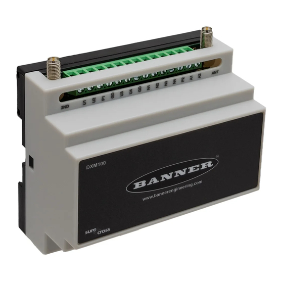
Summary of Contents for Banner Sure Cross DXM100-S Series
- Page 1 ® Sure Cross DXM100-Sx Wireless Modbus Slave Instruction Manual Original Instructions 188231 Rev. F 10 December 2021 © Banner Engineering Corp. All rights reserved 188231...
-
Page 2: Table Of Contents
® Sure Cross DXM100-Sx Wireless Modbus Slave Contents 1 DXM100-Sx Overview ..............................4 1.1 DXM100-S1 System Overview .................................4 1.2 DXM100-S2 System Overview ................................4 1.3 DXM Configuration Software ................................4 1.4 DXM100-Sx Hardware Configuration Overview ..........................5 2 ISM Radio Board (Slave ID 1) ............................7 2.1 DIP Switch Settings for the MultiHop HE5 Board Module ........................7... - Page 3 8.5 FCC and ISED Certification, 2.4GHz ............................. 40 8.6 Notas Adicionales ..................................41 8.7 Mexican Importer ................................... 41 8.8 ANATEL ......................................41 8.9 Contact Us ..................................... 41 8.10 Warnings ......................................42 8.11 Banner Engineering Corp Limited Warranty ..........................42 8.12 Glossary of Wireless Terminology ............................... 43...
-
Page 4: Dxm100-Sx Overview
DXM100-Sx Wireless Modbus Slave 1 DXM100-Sx Overview 1.1 DXM100-S1 System Overview Banner's DXM Logic Controller integrates Banner's wireless radio and local I/O for a remote I/O device. Inputs/Outputs—On-board universal and programmable I/O ports connect to local sensors, indicators, and control Connectivity equipment. -
Page 5: Dxm100-Sx Hardware Configuration Overview
® Sure Cross DXM100-Sx Wireless Modbus Slave Figure 1. Overview of the configuration software features DXM Configuration Software Local Registers Register Mapping Action Rules Scheduler Script Basic System Register Settings View Utility Ethernet XML Config File The configuration software configures the DXM by creating an XML file that is transferred to the DXM using a USB or Ethernet connection. - Page 6 ® Sure Cross DXM100-Sx Wireless Modbus Slave Figure 2. DXM100-Sx hardware overview Housing Catch ISM Radio MultiHop Antenna Radio Board Connection DXM100 I/O Base Board The DXM100 I/O base board provides connections for all inputs, outputs and power. The base board also contains a 12 V solar controller that accepts connections to a solar panel and sealed lead acid (SLA) battery.
-
Page 7: Ism Radio Board (Slave Id 1)
® Sure Cross DXM100-Sx Wireless Modbus Slave 2 ISM Radio Board (Slave ID 1) Plug the ISM radio into the I/O base board with the U.FL antenna connector closest to the SMA connectors. Typically, users will not need to adjust the DIP switch settings on the physical radio modules. For the DXM1200 models, set the radio options using the LCD menu. -
Page 8: Application Mode
® Sure Cross DXM100-Sx Wireless Modbus Slave D1 Switches D2 Switches Device Settings Transmit power OFF* 900 MHz radios: 1.00 Watt (30 dBm) 2.4 GHz radios: 0.065 Watts (18 dBm) and 60 ms frame Transmit power 900 MHz radios: 0.25 Watts (24 dBm) 2.4 GHz radios: 0.065 Watts (18 dBm) and 40 ms frame Application mode: Modbus... -
Page 9: Binding The Ism Radio Of A Modbus Slave
® Sure Cross DXM100-Sx Wireless Modbus Slave 2.2 Binding the ISM Radio of a Modbus Slave A DXM100 (for example, model DXM1x0-S*R2) contains two boards: a MultiHop ISM radio and an I/O base board. Each board is a separate Modbus device and requires a unique Modbus ID. •... -
Page 10: O Base Board For The Dxm100-S1 Model
® Sure Cross DXM100-Sx Wireless Modbus Slave 3 I/O Base Board for the DXM100-S1 Model 3.1 DXM100-S1 I/O Base Board Connections TVS1 A OUT 2 A OUT 1 R118 R122 R121 IC18 No connection Not used N3. NMOS OUT 3 PW. -
Page 11: I/O Board Jumpers For The B1 And S1 Models
® Sure Cross DXM100-Sx Wireless Modbus Slave 3.1.2 I/O Board Jumpers for the B1 and S1 Models Hardware jumpers on the DXM I/O board allow the user to select alternative pin operations. Turn the power off to the device before changing jumper positions. Jumper Function Positions... -
Page 12: Applying Power To The Dxm100-Sx Modbus Slave
® Sure Cross DXM100-Sx Wireless Modbus Slave 3.2 Applying Power to the DXM100-Sx Modbus Slave Apply power to the DXM100-Sx Modbus Slave using either 12 to 30 V DC or a 12 V DC solar panel and 12 V sealed lead acid battery. -
Page 13: Inputs And Outputs
A thermistor input must use a 10k temperature thermistor between ground and the universal input. The thermistor must be a 10k NTC (Banner model number BWA-THERMISTOR-002) or equivalent. Select the temperature conversion of degrees C (default) or degrees F by writing Modbus registers defined in... -
Page 14: Nmos Outputs For The Dxm100
® Sure Cross DXM100-Sx Wireless Modbus Slave Synchronous Counters When an input is configured as a counter (inputs set to NPN/PNP), the input counts the input signal transitions. The count value is stored into two 16-bit Modbus registers for a total count of 32-bits (unsigned). To program an input to capture the edge transition counts, follow Example: Configure Input 1 as a Synchronous Counter on page 14. - Page 15 ® Sure Cross DXM100-Sx Wireless Modbus Slave DXM100/1000-B1 and S1 Models Analog Modbus Description Output Register 0 to 20 mA or 0 to 10 V dc output (I/O board jumper selectable) Accuracy: 0.1% of full scale +0.01% per °C Resolution: 12-bit www.bannerengineering.com - Tel: + 1 888 373 6767...
-
Page 16: O Base Board For The Dxm100-S2 Model
® Sure Cross DXM100-Sx Wireless Modbus Slave 4 I/O Base Board for the DXM100-S2 Model 4.1 I/O Base Board for the B2 and S2 Models TVS1 No connection 2B. DLatch 2B N3. NMOS OUT 3 S-. Secondary RS-485 – (not used for the PW. -
Page 17: Setting The Modbus Slave Id On The I/O Base Board
® Sure Cross DXM100-Sx Wireless Modbus Slave 4.1.2 Setting the Modbus Slave ID on the I/O Base Board Only DXM100-S1 and -S1R2 Slave models require that the Modbus Slave ID to be adjusted on the I/O base board. The DXM100-Sx Modbus Slave models use DIP switches J and K to set the Modbus Slave ID. This device can use a Modbus register 6804 in the I/O board to access the full range of Modbus Slave IDs. -
Page 18: Connecting A Battery
® Sure Cross DXM100-Sx Wireless Modbus Slave 4.2.1 Connecting a Battery When attaching a battery to the DXM100 as a backup battery or as a solar battery, verify the charging algorithm is set properly. The factory default setting for the battery charging algorithm assumes you are using 12 to 30 V DC to recharge the battery. - Page 19 A thermistor input must use a 10k temperature thermistor between ground and the universal input. The thermistor must be a 10k NTC (Banner model number BWA-THERMISTOR-002) or equivalent. Select the temperature conversion of degrees C (default) or degrees F by writing Modbus registers defined in...
-
Page 20: Nmos Outputs For The Dxm100
® Sure Cross DXM100-Sx Wireless Modbus Slave Example: Change Universal Input 2 to a 0 to 10 V dc Input 1. Write a 3 to Modbus register 3326 on Modbus Slave ID 11 (I/O board). 2. Cycle power to the device. 3. -
Page 21: Sdi-12 Interface For The B2 And S2 Models
® Sure Cross DXM100-Sx Wireless Modbus Slave 4.4.5 SDI-12 Interface for the B2 and S2 Models The SDI-12 interface on the B2 Wireless Controllers can support up to five devices with twelve 32-bit register values each. The SDI-12 interface can serial be configured to increase the number of registers per device address for devices with large register sets. - Page 22 In most cases, parameters will not need to be adjusted but if needed there are three common SDI-12 device parameters that control the communications and power of the SDI-12 device. Contact Banner Engineering Corp support for more guidance.
- Page 23 ® Sure Cross DXM100-Sx Wireless Modbus Slave Registers (Default Value) Switch Device Device Warmup Device / Cmd Configuration Enable Power Sample Hi Sample Low Voltage Address Command Time Enable 1753 11001 (48) 6 SDI-12 Device/CMD 1 1751 (1) 1754 (1) 11002 (10) 1752 (0) 1755 (50)
-
Page 24: Additional Information
® Sure Cross DXM100-Sx Wireless Modbus Slave 5 Additional Information 5.1 Adjusting the Receive Slots and Retry Count Parameters The number of receive slots governs how often a MultiHop device can communicate on the wireless network. Battery-powered devices typically have DIP switches that allow the user to set the number of receive slots, which directly affects the battery life of the radio. - Page 25 ® Sure Cross DXM100-Sx Wireless Modbus Slave Modbus Configuration Registers for the Universal Inputs Each input or output on the I/O base board has associated Modbus registers that configure its operation. Universal Input Parameters Registers Universal Inputs Enable Full Scale Registers 3303 3323 3343...
-
Page 26: Modbus I/O Registers For The Dxm100-S2X I/O Base Board
® Sure Cross DXM100-Sx Wireless Modbus Slave Default Output Conditions—Default output triggers are the conditions that drive outputs to defined states. Example default output conditions include when radios are out of sync, when a device cycles power, or during a host communication timeout. •... -
Page 27: Modbus Configuration Registers For The Universal Inputs
® Sure Cross DXM100-Sx Wireless Modbus Slave Base Board Input Connection Modbus Register Range Description 0–65535 Universal input 3 0–65535 Universal input 4 Universal Input Register Ranges Register Types Unit Minimum Value Maximum Value Discrete input/output Universal input 0 to 10 V 10000 * Universal input 0 to 20 mA µA... -
Page 28: Modbus Configuration Registers For The Analog Output
® Sure Cross DXM100-Sx Wireless Modbus Slave 5.2.4 Modbus Configuration Registers for the Analog Output The I/O base board has two analog outputs that are selectable as 0 to 20 mA (factory default) or 0 to 10 V. To change the analog output characteristic, physical jumpers must be change on the I/O board and a parameter Modbus register must be changed. -
Page 29: Modbus Configuration Registers For The I/O (Definitions)
® Sure Cross DXM100-Sx Wireless Modbus Slave Maximum Analog Value—The Maximum Analog Value register stores the maximum allowed analog value. The specific units of measure apply to the register value. For example, the register may contain 20000, for 20 mA, or for a voltage output the register may contain 8000, for 8 volts. -
Page 30: Using Courtesy Power Or Switch Power
® Sure Cross DXM100-Sx Wireless Modbus Slave Table 6: Configuration registers for power Modbus Register Description 6071 Battery backup charging algorithm. 0 = Battery is recharged from a solar panel 1 = Battery is recharged from 12 to 30 V DC (default) 6081 Battery voltage (mV). - Page 31 ® Sure Cross DXM100-Sx Wireless Modbus Slave Switched power 1 and 2 (pins 30 and 21) can be associated to any Universal input to apply power to a sensor, take a reading, and then remove power from the sensor. This conserves power in battery-operated systems. The switched power supply can be used in one of two different ways: supplying courtesy power to an output pin or associated to an input.
-
Page 32: Working With Solar Power
® Sure Cross DXM100-Sx Wireless Modbus Slave Extended Input Read The Extended Input Read is a bit field parameter that allows multiple inputs to be sampled with the same switch power parameters. If the bit field is set to 0x000F, the first four inputs are sampled after the switch power parameters are satisfied. If the Extended Input Read parameter is set in the Universal input 1 configuration registers, set Universal inputs 2 through 4 Extended Input Read and Sample Interval parameters to zero. -
Page 33: Solar Components
Solar Panel Banner solar panels come in two common sizes for the DXM: 5 Watt and 20 Watt. Both panels are designed to work with the DXM but provide different charging characteristics. Use the 5 watt panel for light duty operation and use the 20 watt panel when you require greater charging capabilities. -
Page 34: Recommended Solar Configurations
® Sure Cross DXM100-Sx Wireless Modbus Slave For sites with snow in the winter months, the increased angle helps to shed snow. A solar panel covered in snow produces little or no power. 5.5.3 Recommended Solar Configurations These solar panel and battery combinations assume direct sunlight for at least two to three hours a day. Solar insolation maps provide approximate sun energy for various locations. -
Page 35: Dxm100 And Dxm1000 Dimensions
® Sure Cross DXM100-Sx Wireless Modbus Slave 6 DXM100 and DXM1000 Dimensions All measurements are listed in millimeters, unless noted otherwise. 59.5 mm [2.34”] 20.4 mm 35 mm 104 mm [0.8”] [1.38”] [4.09”] 86 mm [3.39”] 94.6 mm [3.72”] www.bannerengineering.com - Tel: + 1 888 373 6767... -
Page 36: Accessories
® Sure Cross DXM100-Sx Wireless Modbus Slave 7 Accessories For a complete list of all the accessories for the Sure Cross wireless product line, please download the Accessories List (p/n b_3147091). Cordsets Misc Accessories MQDC1-506—5-pin M12/Euro-style, straight, single ended, 6 ft BWA-CG.5-3X5.6-10—Cable Gland Pack: 1/2-inch NPT, Cordgrip for 3 holes of 2.8 to 5.6 mm diam, 10 pack MQDC1-530—5-pin M12/Euro-style, straight, single ended, 30 ft... -
Page 37: Product Support And Maintenance
Ethernet network connection. In a continuing effort to provide the best operation for the DXM100, stay connected with Banner Engineering Corp to hear about the latest updates through the Banner website. Create a login today to stay informed of all Banner product releases. -
Page 38: Firmware Updates
DXM100. Firmware updates and description details are found on the Banner website. Customers with critical update requirements will get access to pre- released firmware from the factory. - Page 39 ® Sure Cross DXM100-Sx Wireless Modbus Slave IMPORTANT: The transmitter modules RM1809 have been certified for fixed base station and mobile applications. If modules will be used for portable applications, the device must undergo SAR testing. IMPORTANT: If integrated into another product, the FCC ID label must be visible through a window on the final device or it must be visible when an access panel, door, or cover is easily removed.
-
Page 40: Fcc And Ised Certification, 2.4Ghz
® Sure Cross DXM100-Sx Wireless Modbus Slave 8.5 FCC and ISED Certification, 2.4GHz This equipment contains transmitter module DX80-2400 or SX243. This device complies with Part 15 of the FCC Rules. Operation is subject to the following two FCC ID: conditions: (1) this device may not cause harmful interference, and (2) this device must accept UE300DX80-2400 any interference received, including interference that may cause undesired operation. -
Page 41: Notas Adicionales
Banner es una marca registrada de Banner Engineering Corp. y podrán ser utilizadas de manera indistinta para referirse al fabricante. "Este equipo ha sido diseñado para operar con las antenas tipo Omnidireccional para una ganancia máxima de antena de 6 dBd y Yagi para una ganancia máxima de antena 10 dBd que en seguida se enlistan. -
Page 42: Warnings
This device has been designed to operate with the antennas listed on Banner Engineering’s website and having a maximum gain of 9 dBm. Antennas not included in this list or having a gain greater that 9 dBm are strictly prohibited for use with this device. -
Page 43: Glossary Of Wireless Terminology
PARTICULAR PURPOSE), AND WHETHER ARISING UNDER COURSE OF PERFORMANCE, COURSE OF DEALING OR TRADE USAGE. This Warranty is exclusive and limited to repair or, at the discretion of Banner Engineering Corp., replacement. IN NO EVENT SHALL BANNER ENGINEERING CORP. BE LIABLE TO BUYER OR ANY OTHER PERSON OR ENTITY FOR... - Page 44 ® Sure Cross DXM100-Sx Wireless Modbus Slave from the master to which it is bound. The binding code defines the network, and all radios within a network must use the same binding code. After binding your MultiHop radios to the master radio, make note of the binding code displayed under the *DVCFG >...
- Page 45 ® Sure Cross DXM100-Sx Wireless Modbus Slave debounce When a signal changes state using a mechanical switch or relay, the signal can oscillate briefly before stabilizing to the new state. The debounce filter examines the signal’s transitions to determine the signal’s state.
- Page 46 ® FlexPower Banner’s FlexPower technology allows for a true wireless solution by allowing the device to operate using either 10 to 30 V DC, 3.6 V lithium D cell batteries, or solar power. This unique power management system can operate a FlexPower Node and an optimized sensing device for up to 5 years on a single lithium D cell.
- Page 47 ® Sure Cross DXM100-Sx Wireless Modbus Slave free space loss The radio signal loss occurring as the signal radiates through free space. Free Space Loss = 20 Log (FSL) (4(3.1416)d/λ ) where d is in meters. Remembering that λf = c = 300 x 10 m/s, the equations reduce down to: For the 900 MHz radio band: FSL = 31.5 + 20 Log d (where d is in meters).
- Page 48 ® Sure Cross DXM100-Sx Wireless Modbus Slave ® hibernation/ While in storage mode, the radio does not operate. To put any integrated battery Sure Cross radio into storage mode storage mode, press and hold button 1 for five seconds. To wake the device, press and hold button 1 for five seconds.
- Page 49 A node is any communications point within a network. Node Nodes are remote I/O slave devices within Banner's wireless sensor networks. Sensors and other devices connect to the Node's inputs or outputs, allowing the Node to collect sensor data and wirelessly transmit it to the Gateway.
- Page 50 ® Sure Cross DXM100-Sx Wireless Modbus Slave and receiver gains are positive numbers and the free space loss is a larger negative number, the total gain of a system should be negative. A link loss calculation may also be called a link budget calculation. peer to peer Peer-to-peer is a model for a communication protocol in which any device in the network can send or network...
- Page 51 ® Sure Cross DXM100-Sx Wireless Modbus Slave sample high/ For analog inputs, the sample high parameter defines the number of consecutive samples the input sample low signal must be above the threshold before a signal is considered active. Sample low defines the number (analog I/O) of consecutive samples the input signal must be below the threshold minus hysteresis before a signal is considered deactivated.
- Page 52 Slave radios acknowledge receipt of messages transmitted from the master radio. For more information on Banner's star network products, refer to the Sure Cross Performance DX80 Wireless I/O Network Instruction Manual (p/n 132607)
- Page 53 ® Sure Cross DXM100-Sx Wireless Modbus Slave threshold and Threshold and hysteresis work together to establish the ON and OFF points of an analog input. The hysteresis threshold defines a trigger point or reporting threshold (ON point) for a sensor input. When the input value is higher than the threshold, the input is ON.
Need help?
Do you have a question about the Sure Cross DXM100-S Series and is the answer not in the manual?
Questions and answers