
Related Manuals for Banner DXM700-B1R1


Summary of Contents for Banner DXM700-B1R1
- Page 1 DXM700-Bx Wireless Controller Instruction Manual March 29, 2023 © Banner Engineering Corp. All rights reserved.
-
Page 2: Table Of Contents
Save and Upload the Configuration File ........13 Banner Engineering Corp Limited Warranty ......13 Chapter: 3 ISM Radio Board (ID 1) . - Page 3 Activating a Cellular Modem ........27 Install the Cellular Modem (DXM100, 150, 700, and 1000 Models) ....28 Install the Cellular Modem (DXM1200 Models) .
- Page 4 Warnings ..........64 Banner Engineering Corp Limited Warranty ......65...
-
Page 5: System Overview Of The Dxm700-Bx
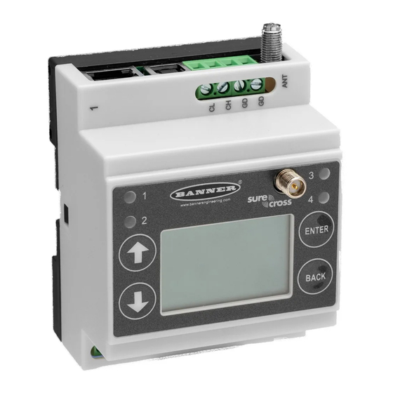
YSTEM VERVIEW OF THE 1. System Overview of the DXM700-Bx Banner's DXM Logic Controller integrates Banner's wireless radio, cellular connectivity, and local I/O to provide a platform for the Industrial Internet of Things (IIoT). DXM700 System Overview Inputs and Outputs... -
Page 6: Dxm Hardware Configuration Overview
The DXM700 base board provides connections for all communications connections, outputs and power/ground. The optional cellular modem is installed in the bottom base board. Attach the antenna cable from the cellular modem to the U.FL connection on the base board. © Banner Engineering Corp. www.bannerengineering.com... -
Page 7: Dxm Automation Protocols
The DXM manages two separate physical ports running the Modbus RTU protocol. The DXM is the Modbus client when operating the Modbus client RTU port. The DXM uses the client Modbus RTU bus to communicate with locally connected Modbus devices or uses the Banner wireless radio to communicate with remote Modbus devices. -
Page 8: Dxm Modbus Registers
Data flash, non-volatile 901–1000 Reserved for internal use 1001–5000 Floating point Floating point registers, local data registers 5001–7000 32-bit integer Local data registers 7001–8000 32-bit non-volatile integer Data flash, non-volatile > 10000 Read-only virtual registers, system-level data © Banner Engineering Corp. www.bannerengineering.com... -
Page 9: Dxm Configuration Software
Gateway and the attached wireless Nodes. Use the MultiHop Configuration Software if the internal radio is a MultiHop device. All tools can be connected to the DXM using a USB cable or an Ethernet connection. © Banner Engineering Corp. www.bannerengineering.com... -
Page 10: Dimensions
[2.29”] 52.8 mm [2.08”] 28.8 mm 35.5 mm DXM700-B1 Cellular radio [1.13”] [1.4”] antenna connection 70 mm [2.76”] 86 mm [3.39”] 94.5 mm DXM700-B2 [3.72”] All measurements are listed in millimeters [inches], unless noted otherwise. © Banner Engineering Corp. www.bannerengineering.com... -
Page 11: Quick Start Guide
Gateway. Enter binding mode on the DXM radio: Use the arrow keys to select the ISM Radio menu on the LCD and press ENTER. Highlight the Binding menu and press ENTER. © Banner Engineering Corp. www.bannerengineering.com... -
Page 12: Bind A Multihop Radio To A Dxm And Assign The Device Id
Repeat these steps, changing the device address, for as many MultiHop radios as are needed for your network. When you are finished binding, press BACK on the DXM until you return to the main menu. All radio devices begin to form the network after the client data radio exits binding mode. ESULT © Banner Engineering Corp. www.bannerengineering.com... -
Page 13: Conduct A Site Survey From The Dxm
If the Site Survey fails (100 missed packets), verify the radios are at least 10 feet from the DXM and/or rerun the binding procedure. If you find poor signal quality, common solutions include moving the DXM to a more central location relative to the Nodes or using higher-gain antennas on the DXM. Contact your local Banner Engineering representative for assistance. 2.1.3. Set a Static IP Address Change the IP address of the DXM to connect to a local area network, Modbus TCP/IP host controller, or EtherNet/IP host controller. -
Page 14: Introduction To Traditional Setup Mode
Discovered DXMs are listed in the network discovery table. Double-click any row entry to connect to that DXM. If the DXM's IP address is already known, the standard TCP connection option is available below the network discovery table. © Banner Engineering Corp. www.bannerengineering.com... -
Page 15: Configuration Example: Reading Registers On A Modbus Server Device
UIDE Banner recommends disconnecting the COMM port through the Device menu before turning off power or disconnecting the USB cable. Use Device > Reboot to restart the DXM if needed; the tool automatically disconnects the COMM port, then reconnect it again. - Page 16 If you connect the DXM to a computer, click Sync PC Time with Device to set the time on the DXM to match the time of the computer. Set your time zone and select whether or not your device observes daylight saving time (DST). © Banner Engineering Corp. www.bannerengineering.com...
-
Page 17: Save And Upload The Configuration File
Banner Engineering Corp. warrants its products to be free from defects in material and workmanship for one year following the date of shipment. Banner Engineering Corp. will repair or replace, free of charge, any product of its manufacture which, at the time it is returned to the factory, is found to have been defective during the warranty period. -
Page 18: Ism Radio Board (Id 1)
Disabling the serial port disables the ISM radio in the DXM700. Selecting Transparent mode causes radio communications to be slower and denies access to device I/O register data. Table 1: DIP switch settings (Sheet 1 of 2) D1 Switches D2 Switches Device Settings Serial line baud rate 19200 OR User defined receiver OFF* OFF* slots © Banner Engineering Corp. www.bannerengineering.com... -
Page 19: Application Mode
(OFF) sets the frame timing to 60 milliseconds. To increase throughput, set the frame timing to 40 milliseconds. For battery-powered devices, increasing the throughput decreases battery life. : Prior to date code 15341 and radio firmware version 3.6, the frame timing was 40 ms (OFF) or 20 ms (ON). IMPORTANT © Banner Engineering Corp. www.bannerengineering.com... -
Page 20: Modbus Registers For The Multihop Radio Board Module
• DXMxxx-xxR3 - DX80 Performance 2.4GHz • DXMxxx-xxR8 - DX80 Performance 900MHz (Australia) : To adjust the transmit power on the Gateway radio, Banner recommends using the LCD menu (System Conf > ISM Radio > RF IMPORTANT CNTRL). Antenna Button... -
Page 21: Modbus Registers For The Performance Gateway Radio Module
Discrete Bit Packed (Status, Discrete Inputs, Discrete Outputs) 6601 through 6753 Analog Inputs (1–8) and Analog Outputs (1–8) 6801 through 9098 3.4.1.1. Input Registers and Outputs Registers Modbus registers 2201 through 2584 are used to organize all inputs together. © Banner Engineering Corp. www.bannerengineering.com... -
Page 22: Discrete Bit-Packed Registers
Input 2 from all devices 6701–6703 Output 2 from all devices 6631–6633 Input 3 from all devices 6711–6713 Output 3 from all devices 6641–6643 Input 4 from all devices 6721–6723 Output 4 from all devices © Banner Engineering Corp. www.bannerengineering.com... -
Page 23: Analog 16-Bit Registers (Registers 6801 Through 9098)
Output 8 for Node 2 For example, 6801 contains the input 1 value for the Gateway, 6802 contains the input 1 value for Node 1, and 6848 contains the input 1 value for Node 47. © Banner Engineering Corp. www.bannerengineering.com... -
Page 24: Processor/Base Board Connections
Press and hold this button for five seconds to send an immediate push message from the device (if properly configured). 4.1. DIP Switch Settings for the Base Board After making changes to the DIP switch settings, cycle power to the device. © Banner Engineering Corp. www.bannerengineering.com... -
Page 25: Ethernet
To move between integers and floats, use the Register Copy Rule. • Local registers 1–850 and 5001–7000 are 32-bit integer registers • Local registers 851–900 and 7001–8000 are non-volatile 32-bit integer registers • Local registers 901-1000 are reserved for internal use © Banner Engineering Corp. www.bannerengineering.com... - Page 26 Http Push SSL Forced Releases 10031–10032 Http Push Attempts Statistical counts of connections, disconnections and forced disconnects when 10033–10034 Http Push Successes the DXM controller creates a connection using HTTP non-encrypted 10035–10036 Http Push Failures © Banner Engineering Corp. www.bannerengineering.com...
- Page 27 Socket x resolver attempts (reserved) 2x013 Socket x resolvers (reserved) 2x015–2x020 Reserved 2x021 Socket x Rule 0 transmits 2x023 Socket x Rule 0 receives 2x025 Socket x Rule 0 timeouts 2x027 Socket x Rule 0 broadcasts © Banner Engineering Corp. www.bannerengineering.com...
-
Page 28: Applying Power To The Dxm700-Bx Wireless Controller
Modbus client device, not the DXM. The server port is used by an external Modbus client device that will access the DXM as a Modbus server device. Use the configuration software to define operational settings for both the Modbus RTU client port and the Modbus RTU server port. © Banner Engineering Corp. www.bannerengineering.com... -
Page 29: Set The Client And Server Port Parameters
Press Enter to accept the ID change. Use the configuration software to cycle power to the device. After cycling power to the device, the updated DXM Modbus ID is listed under the System Config menu. © Banner Engineering Corp. www.bannerengineering.com... -
Page 30: Outputs
Table 6: Modbus Registers for the Base Board Outputs (Modbus ID 203) Modbus Register Range Description 2101 0–1 PNP Output 1 2102 0–1 PNP Output 2 2103 0–1 PNP Output 3 2104 0–1 PNP Output 4 © Banner Engineering Corp. www.bannerengineering.com... -
Page 31: Cellular Modem Boards
Follow these basic steps, as detailed in this document, to activate the cellular capabilities of your DXM Controller. Purchase a cellular modem kit from Banner Engineering Corp. Install the cellular modem, connect the antenna cable, and connect the cellular antenna. -
Page 32: Install The Cellular Modem (Dxm100, 150, 700, And 1000 Models)
SIM provider. For additional information, refer to the Banner Cloud Data Services support center (support.bannercds.com). The support center includes video tutorials, product documentation, technical notes, and links to download configuration software. : Only the DXM100 and DXM150 models in conjunction with an SXI-LTE-001 (obsolete) cellular modem can offer SMS/text IMPORTANT messaging capabilities directly from the device. -
Page 33: Install The Cellular Modem (Dxm1200 Models)
There is a matching notch in the socket and SIM card that will only allow the SIM to be inserted with one orientation. Do not force the SIM card into the socket. © Banner Engineering Corp. www.bannerengineering.com... -
Page 34: Activate A 4G Lte Cat M1 Cellular Plan
Attach the antenna cable between the cellular modem board to the base board. The antenna cable uses the top antenna connection. 5.3.1.3. Activate a 4G LTE CAT M1 Cellular Plan Activate a cellular plan for your DXM700 using the Banner Cloud Data Services website. Go to secure.bannercelldata.com... -
Page 35: Activate A Worldwide 4G Lte M/Nb-Iot Cellular Plan (Red/Ce)
30. However, there may be regions that are not covered by the provided SIM card. In this case, a local SIM card must be activated and operated with this device to acquire connectivity services. Work with the local Banner technical support person to identify and purchase machine-to-machine (M2M) (data plan only) SIM cards in 3FF 'micro' form factor. - Page 36 Many of these solutions execute the data push using a ScriptBasic file instead of the XML configuration file. If you are using a Banner prepackaged solution (ex. SOLUTIONSKIT9-VIBE), then you do not need to set the Cloud Push Interval on the Settings >...
- Page 37 OARDS Obtaining LTE service outside of the Banner Cellular Data Plans—Customers have the option of securing a data plan for the Verizon network themselves without using the Banner cellular data portal (secure.bannercelldata.com). Suitable plans would include those available from Verizon directly or from a Mobile Virtual Network Operator (MVNO) licensed to resell Verizon network data plans.
-
Page 38: Lcd And Menu System
The user can force an immediate push to the webserver using Trigger Push. If a current push is in process it may take several minutes to complete over cellular. • The Trigger Push submenu forces an immediate push to the web server. © Banner Engineering Corp. www.bannerengineering.com... -
Page 39: Ism Radio
Resets Ethernet parameters to xml defaults. Provision Cell to change the value DXM Modbus ID: xxx LCD Contrast: xx to accept ENTER Restart BACK to return to the previous me Figure 5: System Config menu © Banner Engineering Corp. www.bannerengineering.com... -
Page 40: Ism Radio
28. Do not set a number less than 15 or the display may not be bright enough to see to change back. 6.5.5. Reset Use the Restart menu to force the main processor to restart. This does not affect the other boards in the system. © Banner Engineering Corp. www.bannerengineering.com... -
Page 41: System Info
LCD Board Displays the serial number, model, date, firmware part numbers, and version numbers. 6.7. Display Lock Display Lock protects the DXM LCD menu system from being used until the proper pass code is entered. © Banner Engineering Corp. www.bannerengineering.com... -
Page 42: Modbus Registers For The Lcd Board (Modbus Id 201)
LED 4 Amber 1 = On 0 = Off 1107: bit 0 LED 1 Green 1108 : bit 0 LED 2 Green 1109 : bit 0 LED 3 Green 1110 : bit 0 LED 4 Green © Banner Engineering Corp. www.bannerengineering.com... -
Page 43: Working With Modbus Devices
Set the DXM ID from the LCD menu under System > DXM Server ID. The DXM can have any unique ID between 1 and 246, depending upon the host Modbus network. Other RS-485 server port parameters are set in the configuration software under the Settings > General tab. © Banner Engineering Corp. www.bannerengineering.com... -
Page 44: Modbus Operation
DXM700 should wait after a request is sent until the response message is received from the Modbus server device. Use the DXM Configuration Software to set the timeout parameter on the Settings > System screen (select Show advanced settings). The default setting for the timeout parameter is 5 seconds. © Banner Engineering Corp. www.bannerengineering.com... -
Page 45: Multihop Networks Vs Dx80 Star Networks
For a DXM700 with an internal DX80 Gateway, set the timeout value 0.5 seconds. If other Modbus devices are connected to the RS-485 lines, the timeout parameter governs all communication transactions and must be set to accommodate all devices on the bus. © Banner Engineering Corp. www.bannerengineering.com... -
Page 46: Modbus Tcp Client
The DXM700 can operate as a Modbus TCP client on Ethernet. Users may define up to five socket connections for Modbus TCP server devices to read Modbus register data over Ethernet. Use the DXM Configuration Software to define and configure Modbus TCP client communications with other Modbus TCP servers. © Banner Engineering Corp. www.bannerengineering.com... -
Page 47: Configuration Instructions
Start and end times can be specified relative to sunrise and sunset, or set to a specific time within a 24 hour period. When using sunrise or sunset times, set the GPS coordinates on the device so it can calculate sunrise and sunset. © Banner Engineering Corp. www.bannerengineering.com... -
Page 48: Create A One-Time Event
XML configuration file and must be stored in the DXM700. From within the DXM Configuration Software, go to the Settings > Cloud Services screen. In the upper right, select Show advanced settings. © Banner Engineering Corp. www.bannerengineering.com... -
Page 49: Controller Configuration Authentication
The DXM700 register data flow goes through the Local Registers, which are data storage elements that reside within the processor. Using the DXM Configuration Software, the controller can be programmed to move register data from the Local Register pool to remote devices, the internal radio, the I/O base (if applicable), or the display. © Banner Engineering Corp. www.bannerengineering.com... -
Page 50: Basic Approach To Configuration
Device menu. 8.4. EtherNetIP Configuration The DXM700 is defined from the factory to send/receive register data from the Gateway and the first 16 Nodes with an EtherNet/IP™ host. 1. EttherNet/IP is a trademark of Rockwell Automation. © Banner Engineering Corp. www.bannerengineering.com... -
Page 51: Configuring The Host Plc
This allows the user to maximize the use of the EtherNet/IP buffer to 28 devices. EDS (Electronic Data Sheet) files allow users of the EtherNet/IP protocol to easily add a Banner DXM device to the PLC. Download the EDS files from the Banner website. -
Page 52: Define The Network Interface Settings
To use a cellular connection, select Cell as the network connection on the Settings > Cloud Services screen (see Configure the DXM Controller 31). The Cellular screen does not display unless the Network interface is set to Cell. for a Cellular Modem on page © Banner Engineering Corp. www.bannerengineering.com... -
Page 53: Ethernet And Cellular Push Retries
On the Settings > Cellular screen, select your cellular modem from the drop-down list. Set the APN. If you are using a Banner 4G LTE-M Verizon Module (ME910C1), set the APN to ◦ vzwinternet ◦... -
Page 54: Profinet
The PROFINET data type and data size to/from the DXM Controller is configurable. The PROFINET data is processed from the Local Register of the DXM Controller. Configure the IO-Link ports in the XML according to the modules selected for each port © Banner Engineering Corp. www.bannerengineering.com... -
Page 55: Save And Upload The Configuration File
Direction x001 x017 x506 x507 IO-Link In/Out 0x45 0x01 Bidirectional 32/32 Byte + Status x051 x067 x851 x859 x001 x009 x506 x507 IO-Link In/Out 0x46 0x01 Bidirectional 16/16 Byte + Status x051 x059 x851 x859 © Banner Engineering Corp. www.bannerengineering.com... -
Page 56: Example Configuration
3 with PD Size between 1 and 2 bytes Slot 5 Digital Output Use SIO Output mode on Port 4 Slot 10 ISDU 190 Byte + Status ISDU read/write access for all ports in IO-Link mode © Banner Engineering Corp. www.bannerengineering.com... -
Page 57: Configuration Instructions
The Install general station decription file window opens. ESULT Click the More options (...) icon to the right of the Source path field and browse to the location the DXM GSD file was downloaded to. © Banner Engineering Corp. www.bannerengineering.com... -
Page 58: Change The Device Ip Address
FTER OMPLETING If the DXM GSD file does not install properly, save the log and contact Banner Engineering Corp. 9.5.2. Change the Device IP Address Follow these instructions to change the IP address of the DXM device using the Siemens TIA Portal (v14) software. Use these instructions as a basis if you are using another controller (PLC). - Page 59 13. Select Assign IP address under Functions. 14. Click Accessible devices. The Select device window searches the network for available devices. ESULT 15. Determine the device to be adjusted via the MAC address and select it. © Banner Engineering Corp. www.bannerengineering.com...
-
Page 60: Change The Device Name
The Assign PROFINET device name window displays. The software searches for devices of the same type. ESULT Enter the desired name in the PROFINET device name field. Note that each name can be used only once. Click Assign name. The device now has a PROFINET name. ESULT © Banner Engineering Corp. www.bannerengineering.com... -
Page 61: Accessories
BWA-AH12DR—DIN Rail Kit, 12", 2 trilobular/self-threading Class 2, 4-pin female M12 connector screws • PSWB-24-1—DC power supply with multi-blade wall plug,100–240 V AC 50/60 Hz input, 24 V DC 1 A output, UL Listed Class 2, barrel jack connector © Banner Engineering Corp. www.bannerengineering.com... -
Page 62: Product Support And Maintenance
1. While the file download is in process over a USB connection, do not use other applications on the PC. After the DXM reboots for a firmware update, the USB port may be unresponsive. Clear the connection by disconnecting the USB cable and restarting the DXM Configuration Software. © Banner Engineering Corp. www.bannerengineering.com... -
Page 63: Clear The Password On Dxm700-Bx, Dxm1000-Bx, Or Dxm1200-Bx Models
Ethernet network connection. In a continuing effort to provide the best operation for the DXM, stay connected with Banner Engineering Corp to hear about the latest updates through the Banner website. Create a login today to stay informed of all Banner product releases. -
Page 64: Firmware Updates
The DXM has been designed to be a robust and secure IOT device. To provide the most reliable and secure device possible, periodic firmware updates are released to enhance and expand the capabilities of the DXM. Firmware updates and description details are found on the Banner website. -
Page 65: Industry Canada
Antenna types not included in this list that have a gain greater than the maximum gain indicated for any type listed are strictly prohibited for use with this device. © Banner Engineering Corp. www.bannerengineering.com... -
Page 66: Fcc And Ised Certification, 2.4Ghz
Antenna types not included in this list that have a gain greater than the maximum gain indicated for any type listed are strictly prohibited for use with this device. © Banner Engineering Corp. www.bannerengineering.com... -
Page 67: International Certifications For Sure Cross ® Radios
2.4 GHz UE3SX243 FCC ID: UE3SX243: FCC Part 15, Subpart C, 15.247 ® International certifications are not inclusive of all Banner Engineering Sure Cross Radios. For product-specific certifications, contact a local Banner Engineering representative. 11.7.5.1. Mexican Importer Banner Engineering de Mèxico, S. de R.L. de C.V. -
Page 68: Thailand Certification For Dxm700-B1R4 Models
When using other antennas, verify you are not exceeding the transmit power levels allowed by local governing agencies. This device has been designed to operate with the antennas listed on Banner Engineering’s website and having a maximum gain of 9 dBm. Antennas not included in this list or having a gain greater than 9 dBm are strictly prohibited for use with this device. -
Page 69: Banner Engineering Corp Limited Warranty
Banner Engineering Corp. warrants its products to be free from defects in material and workmanship for one year following the date of shipment. Banner Engineering Corp. will repair or replace, free of charge, any product of its manufacture which, at the time it is returned to the factory, is found to have been defective during the warranty period.
Need help?
Do you have a question about the DXM700-B1R1 and is the answer not in the manual?
Questions and answers