Sign In
Upload
Download
Table of Contents
Contents
Add to my manuals
Delete from my manuals
Share
URL of this page:
HTML Link:
Bookmark this page
Add
Manual will be automatically added to "My Manuals"
Print this page
×
Bookmark added
×
Added to my manuals
Manuals
Brands
Banner Manuals
Controller
Sure Cross DXM1200-B Series
Instruction manual
Banner DXM1200-B Series Instruction Manual
Wireless controller
Hide thumbs
Also See for DXM1200-B Series
:
Instruction manual
(73 pages)
1
Table Of Contents
2
3
4
5
6
7
8
9
10
11
12
13
14
15
16
17
18
19
20
21
22
23
24
25
26
27
28
29
30
31
32
33
34
35
36
37
38
39
40
41
42
43
44
45
46
47
48
49
50
51
52
53
54
55
56
57
58
59
60
61
62
63
64
65
66
67
68
69
70
71
72
73
74
75
76
77
78
79
80
81
82
page
of
82
Go
/
82
Contents
Table of Contents
Troubleshooting
Bookmarks
Table of Contents
Table of Contents
Chapter 1 DXM1200-Bx System Overview
DXM1200 Models
DXM Hardware Configuration Overview
DXM Automation Protocols
DXM Modbus Overview
DXM Modbus Registers
DXM Configuration Software
DXM1200 Dimensions
Chapter 2 Quick Start Guide
Device Setup
Apply Power to the Controller
Binding and Conducting a Site Survey with the ISM Radio
Set a Static IP Address
Configuration Instructions
Configuring the DXM1200 Controller
Configuration Example: Reading Registers on a Modbus Server Device
Step 1: Define the Local Registers
Step 2: Read the Registers
Step 3: Define the Time Zone and Set the Time Clock
Step 4: Save the Configuration File
Step 5: Connect the DXM Controller
Step 6: Send the Configuration File to the DXM Controller
Chapter 3 ISM Radio Board (Slave ID 1)
Multihop Radio DIP Switches
Application Mode
Baud Rate and Parity
Disable Serial
Transmit Power Levels/Frame Size
Modbus Registers for the Multihop Radio Board Module
DIP Switch Settings for the Performance Gateway Radio Module
Modbus Registers for the Performance Gateway Radio Module
Alternative Modbus Register Organization
DIP Switch Settings for the Base Board
Ethernet
Usb
Internal Local Registers (ID 199) for the DXM700, DXM1000, and DXM1200
Modbus RTU Client
Chapter 5 Cellular Modem Boards
Cellular Modem Board for LTE
Cellular Power Requirements
Using the DXM Cellular Modem
Activating a Cellular Modem
Registers
Chapter Contents Registers
Push
ISM Radio
System Config
ISM Radio
Ethernet
LCD Contrast
Reset
System Info
Display Lock
Modbus Registers for the LCD (Modbus ID 201)
Chapter 7 Working with Modbus Devices
Assigning Modbus Ids
Modbus Operation
Wireless and Wired Devices
Modbus Communication Timeouts
Multihop Networks Vs DX80 Star Networks
Calculating the Communications Timeout for Battery-Powered Multihop Radios
Calculating the Communication Timeout for 10-30 VDC Multihop Radios
Adjusting the Receive Slots and Retry Count Parameters
Calculating the Communication Timeout for a DX80 Star Network
Modbus TCP Client
Scheduler
Create a Weekly Event
Chapter Contents Scheduler
Create a One-Time Event
Create a Holiday Event
Authentication Setup
Set the Controller to Use Authentication
Controller Configuration Authentication
Register Flow and Configuration
Basic Approach to Configuration
Troubleshooting a Configuration
Saving and Loading Configuration Files
Uploading or Downloading Configuration Files
Ethernet/Ip™ Configuration
Configuring the Host PLC
Configuring the Controller
Define the Network Interface Settings
Configure Your Ethernet Connection
Configure Your Cellular Connection
Ethernet and Cellular Push Retries
Ethernet Push Retries
Cellular Push Retries
Event/Action Rule or Log File Push Retries
Chapter 9 PROFINET
General Station Description Markup Language File
DXM PROFINET IO Data Model
Configure the DXM Controller for a PROFINET IO Connection
Save and Upload the Configuration File
Slots and Modules for the DXMR90-X1, DXM700, DXM1000, and DXM1200 PROFINET
Example Configuration
Install the GSD File
Change the Device IP Address
Change the Device Name
Chapter 10 DXM1200 Accessories
Chapter 11 Product Support and Maintenance
File System and Archive Process
Chapter Contents File System and Archive Process
Update Your DXM Processor Firmware Using the DXM Configuration Software
Clear the Password on DXM700-Bx, DXM1000-Bx, or DXM1200-Bx Models
DXM1200 Documentation
DXM Support Policy
Firmware Updates
Website Information
Feature Requests
Potential DXM Issues
DXM Security
Contact Us
Specifications
Radio Specifications for Performance and Multihop
RS-485 Communication Specifications
DXM1200 Specifications
Environmental Specifications (DXM1200)
FCC and ISED Certification, 900 Mhz, 1 Watt Radios
FCC Notices
FCC and ISED Approved Antennas
FCC and ISED Certification, 2.4Ghz
FCC Notices
FCC and ISED Approved Antennas
Mexican Importer
Anatel
Warnings
Banner Engineering Corp Limited Warranty
Document Information
Advertisement
Quick Links
Download this manual
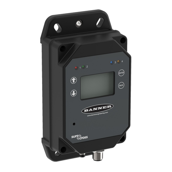
DXM1200-Bx Wireless Controller
Instruction Manual
Original Instructions
p/n: 216539 Rev. J
July 27, 2023
© Banner Engineering Corp. All rights reserved.
Table of
Contents
Previous
Page
Next
Page
1
2
3
4
5
Advertisement
Table of Contents
Need help?
Do you have a question about the DXM1200-B Series and is the answer not in the manual?
Ask a question
Questions and answers
Related Manuals for Banner DXM1200-B Series
Controller Banner Sure Cross DXM700-Bx Instruction Manual
Wireless controller (73 pages)
Controller Banner Sure Cross DXM1200-Bx Instruction Manual
Wireless controller (62 pages)
Controller Banner DXM1200-Bx Instruction Manual
Wireless controller (66 pages)
Controller Banner DXM1200-B1 Instruction Manual
Wireless controller (82 pages)
Controller Banner DXM1200-X2 Instruction Manual
(83 pages)
Controller Banner DXM100 Instruction Manual
(53 pages)
Controller Banner DXM150-S2 Instruction Manual
Wireless modbus slave (43 pages)
Controller Banner Sure Cross DXM150-S Series Instruction Manual
Industrial wireless controller wireless modbus slave (40 pages)
Controller Banner DXM100-S Series Instruction Manual
Wireless modbus slave (45 pages)
Controller Banner DXM100-Bx Instruction Manual
Wireless controller (119 pages)
Controller Banner Sure Cross DXM150 Series Instruction Manual
Wireless controllers (102 pages)
Controller Banner Sure Cross DXM100-B Series Instruction Manual
(121 pages)
Controller Banner Sure Cross DXM100-Bx Instruction Manual
(121 pages)
Controller Banner Sure Cross DXM100-B1 Instruction Manual
(121 pages)
Controller Banner Sure Cross DXM150-Bx Instruction Manual
(107 pages)
Controller Banner DXM150-Bx Instruction Manual
Wireless controller (107 pages)
This manual is also suitable for:
Dxm1200-b1
Dxm1200e-b1
Table of Contents
Print
Rename the bookmark
Delete bookmark?
Delete from my manuals?
Login
Sign In
OR
Sign in with Facebook
Sign in with Google
Upload manual
Upload from disk
Upload from URL


Need help?
Do you have a question about the DXM1200-B Series and is the answer not in the manual?
Questions and answers