
Related Manuals for Banner DXM100-Bx


Summary of Contents for Banner DXM100-Bx
- Page 1 DXM100-Bx and 1000-Bx Wireless Con- troller Instruction Manual Original Instructions p/n: 190037 Rev. M June 05, 2023 © Banner Engineering Corp. All rights reserved.
-
Page 2: Table Of Contents
Contents Chapter 1 Overview System Overview for the DXM100-B1 Models ............................. 5 System Overview for the DXM100-B2 Models ............................. 6 System Overview for the DXM1000-B1 Models ............................7 System Overview for the DXM1000-B2 Models ............................8 Hardware Overview ....................................10 DXM Configuration Software .................................. - Page 3 Activating a Cellular Modem..................................46 Install the Cellular Modem (DXM100, 150, 700, and 1000 Models) ....................47 Install the Cellular Modem (DXM1200 Models) ........................... 48 Activate a 4G LTE CAT M1 Cellular Plan ............................49 Activate a Worldwide 4G LTE MNB-IOT Cellular Plan (RED-CE) ...................... 50 Configure the DXM Controller for a Cellular Modem ..........................
- Page 4 FCC and ISED Certification, 900 MHz, 1 Watt Radios..........................114 FCC Notices ......................................114 FCC and ISED Approved Antennas................................114 FCC and ISED Certification, 2.4GHz................................. 115 FCC Notices ......................................115 FCC and ISED Approved Antennas................................116 ANATEL ........................................116 Warnings........................................116 Banner Engineering Corp Limited Warranty ............................. 117 ............................................118...
-
Page 5: Chapter 1 Overview
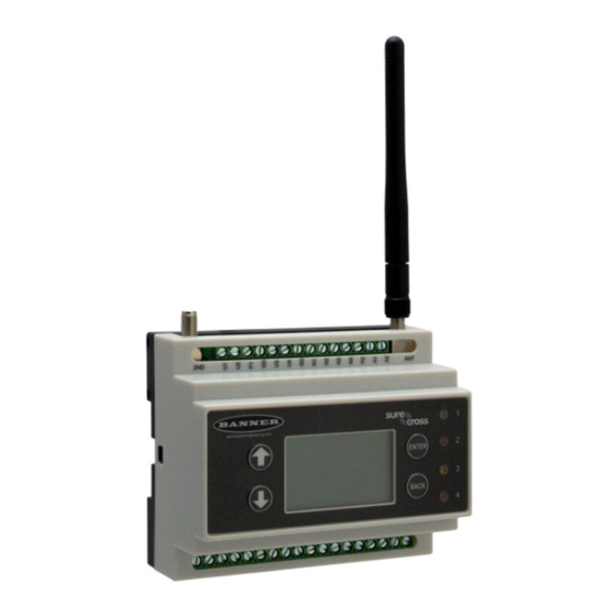
DXM Modbus Overview..................................... 13 Chapter 1 Overview System Overview for the DXM100-B1 Models Banner's DXM Logic Controller integrates Banner's wireless radio, cellular connectivity, and local I/O to provide a platform for the Industrial Internet of Things (IIoT). Inputs and Outputs Connectivity... -
Page 6: System Overview For The Dxm100-B2 Models
Four multicolored LEDs: green, amber, red Viewing sensor information Programmable behavior System Overview for the DXM100-B2 Models Banner's DXM Logic Controller integrates Banner's wireless radio, cellular connectivity, and local I/O to provide a platform for the Industrial Internet of Things (IIoT). Inputs and Outputs Connectivity... -
Page 7: System Overview For The Dxm1000-B1 Models
Four multicolored LEDs: green, amber, and red Viewing sensor Information Programmable behavior System Overview for the DXM1000-B1 Models Banner's DXM Logic Controller integrates Banner's wireless radio, cellular connectivity, and local I/O to provide a platform for the Industrial Internet of Things (IIoT). Inputs and Outputs Connectivity... -
Page 8: System Overview For The Dxm1000-B2 Models
Four defined LED indicators: green , amber, and red Viewing sensor information Programmable behavior System Overview for the DXM1000-B2 Models Banner's DXM Logic Controller integrates Banner's wireless radio, cellular connectivity, and local I/O to provide a platform for the Industrial Internet of Things (IIoT). Inputs and Outputs Connectivity... - Page 9 DXM100-Bx And 1000-Bx Wireless Controller Instruction Manual Continued from page 8 Inputs and Outputs Connectivity Logic Controller User Interface SDI-12 serial interface Modbus registers for internal local registers (Modbus ID 199) Local Registers Type Description 1–845 32-bit integer Local data registers 846–849...
-
Page 10: Hardware Overview
DXM100-Bx And 1000-Bx Wireless Controller Instruction Manual Viewing the system's status User-Defined LED Indicators Four multicolored LEDs: green, amber, and red Programmable behavior Hardware Overview The DXM can have several different configurations. The DXM has a model number label on the housing. Use the model num- ber and model table to identify which boards are included in the your controller. - Page 11 DXM100-Bx And 1000-Bx Wireless Controller Instruction Manual Base Radio Configuration DXM1000- B2 = Smart valve control, SDI-12 data collection Blank = None Power: 12−30 V DC/solar/battery Comms: RS-485, (1) SDI-12 serial interface Inputs: (4) universal IN Not all combinations of base boards and radios are supported.
-
Page 12: Dxm Configuration Software
Modbus RTU protocol. The DXM is the Modbus client when operating the Modbus client RTU port. The DXM uses the client Modbus RTU bus to communicate with locally connect- ed Modbus devices or uses the Banner wireless radio to com- municate with remote Modbus devices. June 05, 2023... -
Page 13: Dxm Modbus Overview
DXM100-Bx And 1000-Bx Wireless Controller Instruction Manual The other Modbus RTU port is used by a host system to ac- Modbus TCP/IP cess the DXM as a server device. The server Modbus RTU A host system acting as a Modbus client can access the DXM port allows access all the internal registers concurrently with using the Modbus TCP/IP protocol over Ethernet. - Page 14 Blank page...
-
Page 15: Chapter 2 Quick Start Guide
DXM100-Bx And 1000-Bx Wireless Controller Instruction Manual Chapter Contents Device Setup ........................................15 Configuration Instructions....................................18 Chapter 2 Quick Start Guide Device Setup Apply Power to the Controller Follow these instructions to apply 12–30 V DC power to the controller using a wall plug. - Page 16 DXM100-Bx And 1000-Bx Wireless Controller Instruction Manual Use the arrow keys to select the ISM Radio menu on the LCD and press ENTER. Highlight the Binding menu and press ENTER. Assign the Node address to the Node. ◦ For Nodes without rotary dials: Use the DXM arrow keys to select the Node address to assign to the DX80 Node about to enter binding mode.
-
Page 17: Set A Static Ip Address
If you find poor signal quality, common solutions include moving the DXM to a more central location relative to the Nodes or using higher-gain antennas on the DXM. Contact your local Banner Engineering representative for assistance. Set a Static IP Address Change the IP address of the DXM to connect to a local area network, Modbus TCP/IP host controller, or EtherNet/IP host controller. -
Page 18: Configuration Instructions
DXM100-Bx And 1000-Bx Wireless Controller Instruction Manual Use this same procedure to set the subnet mask (SN) and default gateway (GW) to match your network requirements. Your IT department can provide these settings if needed. Configuration Instructions Configuring the Controller Configure the DXM using the configuration software. - Page 19 Banner recommends disconnecting the COMM port through the Device menu before turning off power or disconnecting the USB cable. Use Device › Reboot to restart the DXM if needed; the tool automatically disconnects the COMM port, then re- connect it again.
- Page 20 DXM100-Bx And 1000-Bx Wireless Controller Instruction Manual Modify Multiple Registers screen Enter the Starting register and Ending register. Select the value to change using the drop-down list next to each value. Enter the new value in the field provided. To push register values to the web server, set Cloud Settings to Read.
-
Page 21: Save And Upload The Configuration File
DXM100-Bx And 1000-Bx Wireless Controller Instruction Manual Set the Time Use the Settings › System screen to define the time zone and daylight saving option. The time zone and DST options are saved into the configuration file. Settings > System > Device Time Go to the Settings ›... - Page 22 Blank page...
-
Page 23: Chapter 3 Ism Radio Board (Id 1)
DXM100-Bx And 1000-Bx Wireless Controller Instruction Manual Chapter Contents MultiHop Radio DIP Switches ................................... 23 DIP Switch Settings for the Performance Gateway Radio Module........................25 Chapter 3 ISM Radio Board (ID 1) Plug the ISM radio into the I/O base board with the U.FL antenna connector closest to the SMA connectors. Typically, users will not need to adjust the DIP switch settings on the physical radio modules. -
Page 24: Application Mode
DXM100-Bx And 1000-Bx Wireless Controller Instruction Manual Disabling the serial port disables the ISM radio in the DXM. Selecting Transparent mode causes radio communications to be slower and denies access to device I/O register data. DIP switch settings D1 Switches... -
Page 25: Disable Serial
DXMxxx-xxR3 - DX80 Performance 2.4GHz • DXMxxx-xxR8 - DX80 Performance 900MHz (Australia) IMPORTANT: To adjust the transmit power on the Gateway radio, Banner recommends using the LCD menu (System Conf › ISM Radio › RF CNTRL). DIP switch bank 1 and bank 2... - Page 26 Blank page...
-
Page 27: Chapter 4 Processor Board
DXM100-Bx And 1000-Bx Wireless Controller Instruction Manual Chapter Contents Processor Board for the DXM1x0 Models ................................. 27 Processor Board for the DXM1x00 Models ............................... 28 DIP Switch Settings for the Processor Board..............................28 Ethernet ..........................................29 USB ..........................................29 Chapter 4... -
Page 28: Processor Board For The Dxm1X00 Models
DXM100-Bx And 1000-Bx Wireless Controller Instruction Manual Continued from page 27 Callout Description Function Indicates the cellular modem power cutoff is active; if the incoming power is less than 11.2 V, the cellular modem LED 2 is powered down XML configuration file was rejected; or file load in process; or the second phase of boot loading is in process... -
Page 29: Ethernet
Config › Ethernet › Reset menu. The USB port is used with the DXM Configuration Software to program the DXM100-Bx or 1000-Bx Wireless Controller. The USB port is also used as the console output for the processor and ScriptBasic. - Page 30 Blank page...
-
Page 31: I/O Base Board Connections For The B1 Models
DXM100-Bx And 1000-Bx Wireless Controller Instruction Manual Chapter Contents I/O Base Board Connections for the B1 Models..............................31 I/O Base Board for the B2 and S2 Models ................................ 32 DIP Switches for the IO Board ..................................33 Setting the Modbus ID on the IO Base Board ..............................33 I/O Board Jumpers for the B1 and S1 Models.............................. -
Page 32: I/O Base Board For The B2 And S2 Models
DXM100-Bx And 1000-Bx Wireless Controller Instruction Manual Continued from page 31 P1. Adjustable Courtesy Power (5 V or GD. Ground A2. Analog OUT 2 16 V) TX. RS-232 Tx A1. Analog OUT 1 U2. Universal Input 2 P2. Adjustable Courtesy Power (5 V or RX. -
Page 33: Dip Switches For The Io Board
Bx or 1000-Bx Wireless Controller models use DIP switches J and K to set the Modbus ID. This device can use a Modbus register 6804 in the I/O board to access the full range of Modbus IDs. On the DXM100-Bx or 1000-Bx Wireless Controller models, use the DIP switches at location K to define the lower digit of the Modbus ID. -
Page 34: I/O Board Jumpers For The B1 And S1 Models
4028 on the I/O board (SID 200) to 3. Applying Power Apply power to the DXM100-Bx or 1000-Bx Wireless Controller using either 12 to 30 V DC or a 12 V DC solar panel and 12 V sealed lead acid battery operating together. -
Page 35: Supplying Power From A Solar Panel
Supplying Power from a Solar Panel To power the DXM100-Bx or 1000-Bx Wireless Controller from a 12 V DC solar panel, connect the solar panel to power pins 2(+) and 3(-). Connect a 12 V DC sealed lead acid (SLA) rechargeable battery to pins 4(+) and 5(-). -
Page 36: Set The Client And Server Port Parameters
DXM100-Bx And 1000-Bx Wireless Controller Instruction Manual • As a Modbus RTU server device, the DXM local registers can be read from or written to by another Modbus RTU client device. The secondary port (S+/S-) is the Modbus RTU server connection. The secondary (server) Modbus RS-485 port (S+/S-) is controlled by another Modbus client device, not the DXM. -
Page 37: Inputs And Outputs
"Modbus Register Summary " on page 74 for more descriptions of each Modbus register on the DXM100-Bx or 1000-Bx Wireless Controller. Universal Inputs The universal inputs on the DXM100-Bx or 1000-Bx Wireless Controller can be programmed to accept several different types of inputs: • Discrete NPN/PNP •... - Page 38 DXM100-Bx And 1000-Bx Wireless Controller Instruction Manual NPN vs NPN Raw Fast Synchronous Counters The difference between NPN and NPN Raw Fast is the When an input is configured as a counter (inputs set to NPN/ amount of settling time given to the input. Switch the input PNP), the input counts the input signal transitions.
-
Page 39: Nmos Outputs For The Dxm100
DXM100-Bx And 1000-Bx Wireless Controller Instruction Manual NMOS Outputs for the DXM100 NMOS output pins for the DXM100 models NMOS Discrete Modbus Register Description Wiring Outputs Output Less than 1 A maximum current at 30 V DC ON-State Saturation: Less than 0.7 V at 20 mA ON Condition: Less than 0.7 V... -
Page 40: Sdi-12 Interface For The B2 And S2 Models
DXM100-Bx And 1000-Bx Wireless Controller Instruction Manual The DXM Configuration Software allows the user to adjust parameters that govern the operation of the DC latch outputs. Most applications will not require any changes for correct operation. Software parameters include: •... - Page 41 DXM100-Bx And 1000-Bx Wireless Controller Instruction Manual Continued from page 40 SDI-12 Command Register Value xM8! xM9! Supported C! commands SDI-12 Command Register Value 1 or 20 xC1! xC2! xC3! xC4! xC5! xC6! xC7! xC8! xC9! The Modbus configuration registers are listed. All registers are defined as Modbus holding registers. The factory default val- ues are shown in parentheses.
- Page 42 In most cases, parameters will not need to be adjusted but if needed there are three common SDI-12 de- vice parameters that control the communications and power of the SDI-12 device. Contact Banner Engineering Corp support for more guidance.
- Page 43 DXM100-Bx And 1000-Bx Wireless Controller Instruction Manual Models Technical Note Acclima SEN-SDI (TDT SDI-12 Soil Moisture Sensor) SDI-12 and the Acclima TDT SDI-12 Soil Moisture Probe (p/n b_4182040) Adcon Telemetry HydraProbeII SDI-12 and the AquaCheck Sub-Surface Soil Moisture Probe (p/n...
- Page 44 Blank page...
-
Page 45: Chapter 6 Cellular Modem Boards
DXM100-Bx And 1000-Bx Wireless Controller Instruction Manual Chapter Contents Cellular Modem Board....................................... 45 Cellular Power Requirements ................................... 45 Using the DXM Cellular Modem ..................................46 Activating a Cellular Modem....................................46 Chapter 6 Cellular Modem Boards Cellular Modem Board The LTE-M (United States) or LTE-M/NB-IoT (outside the United States) cellular modem is an optional accessory that is in- stalled on the processor board on the two 12-pin sockets. -
Page 46: Using The Dxm Cellular Modem
Follow these basic steps, as detailed in this document, to activate the cellular capabilities of your DXM Controller. Purchase a cellular modem kit from Banner Engineering Corp. Install the cellular modem, connect the antenna cable, and connect the cellular antenna. -
Page 47: Install The Cellular Modem (Dxm100, 150, 700, And 1000 Models)
SIM provider. For additional information, refer to the Banner Cloud Data Services support center (support.bannercds.com). The support center includes video tutorials, product documentation, technical notes, and links to download configuration software. IMPORTANT: Only the DXM100 and DXM150 models in conjunction with an SXI-LTE-001 (obsolete) cel- lular modem can offer SMS/text messaging capabilities directly from the device. -
Page 48: Install The Cellular Modem (Dxm1200 Models)
DXM100-Bx And 1000-Bx Wireless Controller Instruction Manual DXM100, 150, and 1000 DXM700 Antenna Cable Modem Modem Antenna Cable *SIM card is located on the underside of installed modem *SIM card is located on the underside of installed modem ◦ For the DXM100, DXM150, and DXM1000 models—Install the cellular modem board onto the processor board as shown. -
Page 49: Activate A 4G Lte Cat M1 Cellular Plan
Attach the antenna cable between the cellular modem board to the base board. The antenna cable uses the top an- tenna connection. Activate a 4G LTE CAT M1 Cellular Plan Activate a cellular plan for your DXM using the Banner Cloud Data Services website. Go to celldata.bannercds.com to purchase cellular data plans. -
Page 50: Activate A Worldwide 4G Lte Mnb-Iot Cellular Plan (Red-Ce)
For regions outside of North America—Select SXI-CATM1WW-001 and set the APN to m2m.tele2.com when using the SIM card provided with the kit from Banner Engineering. When using a local roaming SIM, please use the APN as suggested by your cellular connectivity (SIM) provider. - Page 51 Data Services web-based software platform via cellular connectivity. Many of these solutions execute the data push using a ScriptBasic file instead of the XML configuration file. If you are using a Banner prepack- aged solution (ex. SOLUTIONSKIT9-VIBE), then you do not need to set the Cloud Push Interval on the Settings › Cloud Services screen.
- Page 52 Blank page...
-
Page 53: Registers
DXM100-Bx And 1000-Bx Wireless Controller Instruction Manual Chapter Contents Registers .......................................... 53 Push ..........................................54 ISM Radio ......................................... 54 IO Board ........................................... 55 System Config ........................................56 System Info ........................................59 Display Lock ........................................60 Chapter 7 LCD and Menu System The LCD has four user-defined LED indicators, four control buttons, and an LCD. -
Page 54: Push
DXM100-Bx And 1000-Bx Wireless Controller Instruction Manual Read allows the register to be displayed and Write or Read/Write allows the register value to be changed using the LCD. The Units and Scaling parameters are optional and affect the LCD. Push The Push menu displays information about the last data sent to the Webserver. -
Page 55: Io Board
DXM100-Bx And 1000-Bx Wireless Controller Instruction Manual IO Board Use the I/O Board menu to view input values, output values, input counters values, and the charger status on the DXM I/O board. To change the configuration parameters, use the System Config menu. -
Page 56: System Config
DXM100-Bx And 1000-Bx Wireless Controller Instruction Manual System Config Use the System Config menu to set DXM system parameters. System Config menu New ISM Modbus ID: x ISM Radio DX80 ID: x System Config Auto Detect Radio ID: 1 Advanced Options... -
Page 57: Io Board
DXM100-Bx And 1000-Bx Wireless Controller Instruction Manual Binding #—This parameter allows the user to define the Binding code within the ISM radio. Typically, you will not have to ad- just this number unless you are replacing an existing Gateway or client radio. -
Page 58: Ethernet
DXM100-Bx And 1000-Bx Wireless Controller Instruction Manual Ethernet Use the Ethernet submenu to sets the IP Address, Gateway Address, and Subnet mask of the DXM's Ethernet interface. You may change these settings either from the LCD menu (System Config › Ethernet) or from the XML configuration file created by the DXM Configuration Software. -
Page 59: System Info
DXM100-Bx And 1000-Bx Wireless Controller Instruction Manual System Info Various DXM system settings are shown in this menu. The Push, Ethernet, and Cell parameters are helpful for debugging network connections. This is a read only menu. System Info menu System Info... -
Page 60: Display Lock
DXM100-Bx And 1000-Bx Wireless Controller Instruction Manual Display Lock Display Lock protects the DXM LCD menu system from being used until the proper pass code is entered. Display Lock menu Display Lock Enter password ↑ ↓ >> x to change the value... -
Page 61: Chapter 8 Configuration Instructions
DXM100-Bx And 1000-Bx Wireless Controller Instruction Manual Chapter Contents DXM Configuration Software..................................... 12 Save and Upload the Configuration File................................21 Register Flow and Configuration ..................................62 Scheduler .......................................... 63 Authentication Setup ......................................65 EtherNetIP Configuration ....................................66 Define the Network Interface Settings................................68 Ethernet and Cellular Push Retries ................................... -
Page 62: Register Flow And Configuration
DXM100-Bx And 1000-Bx Wireless Controller Instruction Manual Save and Upload the Configuration File After making any changes to the configuration, you must save the configuration files to your computer, then upload it to the device. Changes to the XML file are not automatically saved. Save your configuration file before exiting the tool and before sending the XML file to the device to avoid losing data. -
Page 63: Troubleshooting A Configuration
DXM100-Bx And 1000-Bx Wireless Controller Instruction Manual ferent functions to the Local Register data, including conditional statements, math operations, copy operations, or trending. To perform scheduled events in Local Registers, go to the Scheduler screen in the DXM Configuration Software. -
Page 64: Create A One-Time Event
DXM100-Bx And 1000-Bx Wireless Controller Instruction Manual Click on the arrow to the left of the new rule to expand the parameters into view. The user-defined parameters are displayed. Name your new rule. Enter the local register. Select the days of the week this rule applies to. -
Page 65: Authentication Setup
DXM100-Bx And 1000-Bx Wireless Controller Instruction Manual Authentication Setup The DXM has three different areas that can be configured to require a login and password authentication. • Webserver/ Cloud Services Authentication • Mail Server Authentication • DXM Configuration Authentication The webserver and mail server authentication depends upon the service provider. -
Page 66: Ethernetip Configuration
This allows the user to maximize the use of the EtherNet/IP buffer to 28 devices. EDS (Electronic Data Sheet) files allow users of the EtherNet/IP protocol to easily add a Banner DXM device to the PLC. Download the EDS files from the Banner website. - Page 67 DXM100-Bx And 1000-Bx Wireless Controller Instruction Manual EIP Assembly Instance 112 (16-bit) DXM Local Registers Adrs Data Adrs Data 1122 1122 3344 3344 5566 5566 7788 7788 9900 9900 Data from the DXM local registers is sent to the EIP controller using assembly instance 100. Each local register in the DXM defined as EIP DXM ›...
-
Page 68: Configuring The Host Plc
The Originator is the host PLC system, and the DXM is the DXM. The host system sees the DXM as a generic device with the product name of Banner DXM (ProdType: 43 - Generic Device, ProdName: Banner DXM, Integer Type - INT). -
Page 69: Configure Your Cellular Connection
On the Settings › Cellular screen, select your cellular modem from the drop-down list. Set the APN. ◦ If you are using a Banner 4G LTE-M Verizon Module (ME910C1), set the APN to vzwinternet. ◦ If you are using a Banner 4G LTE AT&T Module (ME910C1), set the APN to iot0119.com.attz. -
Page 70: Cellular Push Retries
DXM100-Bx And 1000-Bx Wireless Controller Instruction Manual to be sent later. After 10 rounds of retries, the data set is archived on the micro SD card under folder _sxi. No additional at- tempts to resend the data are made; the data file must be manually retrieved. -
Page 71: Chapter 9 Additional Information
DXM100-Bx And 1000-Bx Wireless Controller Instruction Manual Chapter Contents Working with Modbus Devices ..................................71 Modbus Register Summary....................................74 Using Courtesy Power or Switch Power ................................90 Associating a Switched Power Output to an Input ............................90 Associate Universal Input 1 with Switch Power 1.............................. 92 Working with Solar Power .................................... -
Page 72: Assigning Modbus Ids
DXM100-Bx And 1000-Bx Wireless Controller Instruction Manual The DXM operates the Modbus client port. Each device on the client port must be assigned a unique Modbus ID. There are Modbus IDs that are reserved for internal devices in the DXM. -
Page 73: Modbus Communication Timeouts
DXM100-Bx And 1000-Bx Wireless Controller Instruction Manual Continued from page 72 Modbus ID Description Allocated for the I/O base board; will be different for special DXM server-only models. Allocated for the LCD display board, the user can read/write LEDs. Modbus Communication Timeouts A Modbus timeout is the amount of time a Modbus server is given to return an acknowledgment of a message sent by the Modbus client. -
Page 74: Modbus Tcp Client
DXM100-Bx And 1000-Bx Wireless Controller Instruction Manual Using the timeout calculation above of 23 seconds, if a repeater is added to the network the timeout should be set to 25 sec- onds. For each additional MultiHop repeater device creating another level of network hierarchy, add an additional two sec- onds to the timeout period. -
Page 75: Modbus Registers For The Multihop Radio Board Module
DXM100-Bx And 1000-Bx Wireless Controller Instruction Manual Modbus Registers for the MultiHop Radio Board Module The DX80 MultiHop client radio is a tree-based architecture device that allows for repeater radios to extend the wireless net- work. Each device in a MultiHop network is a Modbus device with a unique Modbus ID. - Page 76 DXM100-Bx And 1000-Bx Wireless Controller Instruction Manual Access all wireless network registers by reading Modbus ID 1 DX80 Device Modbus ID Modbus Registers DXM Gateway radio Modbus registers 1–8 are inputs, 9–16 are outputs Node 1 Modbus registers 17–24 are inputs, 25–32 are outputs Node 2 Modbus registers 33–40 are inputs, 41–48 are outputs...
- Page 77 DXM100-Bx And 1000-Bx Wireless Controller Instruction Manual Discrete bit-packed register addresses and bit positions Bit-P acked Device Status Registers Bit Position Register Address 6601 Node 15 Node 14 Node 13 Node 12 Node 11 Node 10 Node 9 Node 8...
-
Page 78: Internal Local Registers (Id 199) For The Dxm100 And Dxm150
DXM100-Bx And 1000-Bx Wireless Controller Instruction Manual Analog 16-Bit Registers (Registers 6801 through 9098) The most efficient way to read (or write) analog data from a Gateway is by using these 16-bit analog registers. Most networks consist of similar Nodes reporting data using the same I/O registers for each Node. For this reason, the analog data is arranged by I/O point using Modbus registers 6801 through 9098. - Page 79 DXM100-Bx And 1000-Bx Wireless Controller Instruction Manual Modbus Registers for Internal Local Registers (Modbus ID 199) Local Registers Type Description 1–845 32-bit unsigned Internal processor memory 846–849 32-bit unsigned Reset, Constant, Timer 851–900 32-bit unsigned Data flash, non-volatile 1001–1900 32-bit IEEE Floating Point Floating point registers, internal processor memory >...
- Page 80 DXM100-Bx And 1000-Bx Wireless Controller Instruction Manual Continued from page 79 Virtual Registers Definition 10029–10030 Http Push SSL Forced Releases 10031–10032 Http Push Attempts Statistical counts of connections, disconnections and forced disconnects when 10033–10034 Http Push Successes the DXM controller creates a connection using HTTP non-encrypted 10035–10036...
-
Page 81: Internal Local Registers (Id 199) For The Dxm700, Dxm1000, And Dxm1200
DXM100-Bx And 1000-Bx Wireless Controller Instruction Manual The reset codes are in virtual register 11015 and define the condition of the last restart operation. Reset Code Definition Undefined Unknown General Brownout Watchdog User Software Return from backup mode Internal Local Registers (ID 199) for the DXM700, DXM1000, and DXM1200 The main storage elements for the DXM are its local registers, which can store 4-byte values that result from register map- ping, action rules, or ScriptBasic commands. - Page 82 DXM100-Bx And 1000-Bx Wireless Controller Instruction Manual Local registers 1001–5000— These local registers are paired together to store a 32-bit IEEE floating point format number in big-endian format. Registers 1001 [31:16], 1002 [15:0] store the first floating point value; registers 1003, 1004 store the sec- ond floating point number.
- Page 83 DXM100-Bx And 1000-Bx Wireless Controller Instruction Manual Continued from page 82 Registers Definition 10103 Number of read map errors 10104 Read map success streak 10105 Number of write map successes 10106 Number of write map timeouts Write Map statistics 10107...
-
Page 84: Modbus Io Registers For The B1 Io Base Board
DXM100-Bx And 1000-Bx Wireless Controller Instruction Manual Continued from page 83 Register Definition 2x029 Reserved 2x031 Socket x Rule 1 transmits 2x033 Socket x Rule 1 receives 2x035 Socket x Rule 1 timeouts 2x037 Socket x Rule 1 broadcasts 2x039 Reserved Reset Codes—The reset codes are in virtual register 11015 and define the condition of the last restart operation. -
Page 85: Modbus Io Registers For The B2 Io Base Board
DXM100-Bx And 1000-Bx Wireless Controller Instruction Manual B1 Controller Base Board Output Connection Modbus Register Range Description 0–1 NMOS Output 1 0–1 NMOS Output 2 0–1 NMOS Output 3 0–1 NMOS Output 4 0–1 Switched Power 1 (5 V or 16 V) 0–1... -
Page 86: Modbus Configuration Registers For The Universal Inputs
DXM100-Bx And 1000-Bx Wireless Controller Instruction Manual Continued from page 85 B2 Controller Base Board Output Connection Modbus Register Range Description 0–10000 Analog Output 1 (0-10.000 V) 0–10000 Analog Output 2 (0-10.000 V) Modbus Configuration Registers for the Universal Inputs Each input or output on the I/O base board has associated Modbus registers that configure its operation. -
Page 87: Modbus Configuration Registers For The Io (Definitions)
DXM100-Bx And 1000-Bx Wireless Controller Instruction Manual Continued from page 86 Analog output Analog output 2 Description Values Enable Default Communica- 0 = Disable 2952 tion Timeout 1 = Enable Communication Default I/O 2953 Number of 100 ms periods Timeout (100 ms/Count) -
Page 88: Modbus Configuration Registers For Power
DXM100-Bx And 1000-Bx Wireless Controller Instruction Manual Hysteresis and Threshold Input Type Threshold and hysteresis work together to establish the ON Program the universal inputs to accept input types NPN, PNP, and OFF points of an analog input. The threshold defines a 10k thermistor, 0 to 10 V, 0 to 20 mA, or potentiometer. - Page 89 DXM100-Bx And 1000-Bx Wireless Controller Instruction Manual Using the configuration software, go to the Local Registers › Local Registers in Use screen. Define the local registers by assigning names to the first four registers and setting the LCD permissions parameter to read/write.
-
Page 90: Using Courtesy Power Or Switch Power
Using Courtesy Power or Switch Power Pin 18 of the DXM100-Bx or 1000-Bx Wireless Controller is a constant power source that supplies 5 volts up to 500 mA. Pins 21 (switch power 2) and 30 (switch power 1) are switched power outputs. Configure the switched power outputs using Modbus registers or by using the DXM Configuration Software's Settings ›... - Page 91 DXM100-Bx And 1000-Bx Wireless Controller Instruction Manual Cycle power if this register value is changed. Voltage For the B1 and S1 models, set the Modbus register value to 0 Output Register for a switched power supply at 5 volts. Set the Modbus regis- Write to the Output register to turn on or turn off the voltage ter value to 1 for a switched power supply at 16 volts.
-
Page 92: Associate Universal Input 1 With Switch Power 1
DXM100-Bx And 1000-Bx Wireless Controller Instruction Manual Associate Universal Input 1 with Switch Power 1 To associate universal input 1 with switched power 1, follow these instructions. Set Input 1 to sample every 60 seconds, with a warmup time of 10 seconds. -
Page 93: Solar Panel
Solar Panel Banner solar panels come in two common sizes for the DXM: 5-watt and 20-watt. Both panels are designed to work with the DXM but provide different charging characteristics. Use the 5-watt panel for light-duty operation and use the 20-watt panel when you require greater charging capabilities. -
Page 94: Recommended Solar Configurations
DXM100-Bx And 1000-Bx Wireless Controller Instruction Manual Recommended Solar Configurations These solar panel and battery combinations assume direct sunlight for at least two to three hours a day. Solar insolation maps provide approximate sun energy for various locations. The depth of battery discharge is assumed to be 50 percent. -
Page 95: Clear The Password On Dxm700-Bx, Dxm1000-Bx, Or Dxm1200-Bx Models
DXM100-Bx And 1000-Bx Wireless Controller Instruction Manual IMPORTANT: DO NOT follow these instructions if you have a DXM700, DXM1000, or DXM1500 model. If you attempt to clear the password of a DXM700, DXM1000, or DXM1500 with these instructions, the firmware of your device will be erased and your controller will no longer function. - Page 96 Blank page...
-
Page 97: Chapter 10 Profinet
DXM100-Bx And 1000-Bx Wireless Controller Instruction Manual Chapter Contents General Station Description Markup Language File ............................97 DXM PROFINET IO Data Model ..................................97 Configure the DXM Controller for a PROFINET IO Connection ........................97 Slots and Modules for DXM PROFINET ................................98 Configuration Instructions .................................... -
Page 98: Slots And Modules For Dxm Profinet
DXM100-Bx And 1000-Bx Wireless Controller Instruction Manual Status indicator bar ◦ If the Application Status indicator is red, close and restart the DXM Configuration Tool, unplug and re-plug in the cable and reconnect the DXM to the software. ◦ If the Application Status indicator is green, the file upload is complete. - Page 99 DXM100-Bx And 1000-Bx Wireless Controller Instruction Manual Continued from page 98 Size Module ID Submodule ID Module Register Start Register End Direction (bytes) x506 x507 x051 x055 x851 x859 x001 x003 x506 x507 0x48 0x01 IO-Link In/Out 4/4 Byte + Status...
-
Page 100: Install The Gsd File
DXM100-Bx And 1000-Bx Wireless Controller Instruction Manual Continued from page 99 Example Configuration Slot Module Description Slot 5 Digital Output Use SIO Output mode on Port 4 Slot 10 ISDU 190 Byte + Status ISDU read/write access for all ports in IO-Link mode... - Page 101 The system installs the DXM GSD file and places it in the Hardware catalog. In the example, the DXM GSD file is lo- cated under Other field devices › PROFINET IO › Banner Engineering Corp. › Banner. If the DXM GSD file does not install properly, save the log and contact Banner Engineering Corp. June 05, 2023...
-
Page 102: Change The Device Ip Address
DXM100-Bx And 1000-Bx Wireless Controller Instruction Manual Change the Device IP Address Follow these instructions to change the IP address of the DXM device using the Siemens TIA Portal (v14) software. Use these instructions as a basis if you are using another controller (PLC). - Page 103 DXM100-Bx And 1000-Bx Wireless Controller Instruction Manual Online & diagnostics menu and screen The Online & diagnostics windows displays. Select Assign IP address under Functions. Click Accessible devices. The Select device window searches the network for available devices. Determine the device to be adjusted via the MAC address and select it.
-
Page 104: Change The Device Name
DXM100-Bx And 1000-Bx Wireless Controller Instruction Manual Change the Device Name Follow these instructions to change the name of the DXM using the Siemens TIA Portal (v14) software. Use these instruc- tions as a basis if you are using another controller (PLC). -
Page 105: Accessories
DXM100-Bx And 1000-Bx Wireless Controller Instruction Manual Chapter Contents Accessories ........................................105 DXM100 and DXM1000 Dimensions................................106 File System and Archive Process ................................... 106 Troubleshooting....................................... 107 DXM100 Documentation ....................................112 DXM1000 Documentation ....................................112 DXM Support Policy ......................................113 Contact Us........................................113 Mexican Importer...................................... -
Page 106: Dxm100 And Dxm1000 Dimensions
DXM100-Bx And 1000-Bx Wireless Controller Instruction Manual Continued from page 105 Power Supplies Enclosures and DIN Rail Kits PSD-24-4—DC Power Supply, Desktop style, 3.9 A, 24 V DC, Class 2, BWA-AH864—Enclosure, Polycarbonate, with Opaque Cover, 8 × 6 × 4 4-pin M12 quick disconnect (QD) BWA-AH1084—Enclosure, Polycarbonate, with Opaque Cover, 10 ×... -
Page 107: Troubleshooting
DXM100-Bx And 1000-Bx Wireless Controller Instruction Manual • CmVMon file • _sxi Archive directory Data Log files CmVMon File Users may create up to four data log files using the DXM Con- The CmVMon.txt file (Cellular milli-Volt Monitor) is created by figuration Software. - Page 108 DXM100-Bx And 1000-Bx Wireless Controller Instruction Manual Update Your DXM Processor Firmware (Prior to Version 2.0) To update DXM Processor firmware prior to version 2.0, use the SAM-BA program from MicroChip/Atmel. Following these in- structions to update the DXM100 or DXM150 processor firmware.
- Page 109 DXM100-Bx And 1000-Bx Wireless Controller Instruction Manual SAM-BA popup window In the SCRIPTS pull-down menu, select BOOT FROM FLASH (GPNVM1). Click EXECUTE. Click EXECUTE again if the message indicates it failed. In the Flash tab, click on the folder icon for the Send File Name field. Select the boot load file (must be a *.bin file) and click SEND FILE.
- Page 110 DXM100-Bx And 1000-Bx Wireless Controller Instruction Manual Update process overview Reprogramming Step Approximate time required Description configuration software: 2 minutes over Ethernet Send the new firmware image to the DXM. After the new im- or 15 minutes over USB Loading new firmware file (*.HEX) age is on the device, the controller resets.
- Page 111 DXM100-Bx And 1000-Bx Wireless Controller Instruction Manual From the main Dashboard › Sites screen, click on Update. A popup box appears. Set the Communications Type to Push Reply, and set the Update Type to Firmware file. Choose the appropriate Upload File (*.HEX) and click Queue. Click Close.
-
Page 112: Troubleshooting Issues
DXM100-Bx And 1000-Bx Wireless Controller Instruction Manual Troubleshooting Issues Problem Solution The LCD and the processor applications share the external Modbus connection. If the processor is configured to constantly interact with Modbus, it may cause issues with the LCD attempting to use the functions of the ISM radio. -
Page 113: Dxm Support Policy
Banner website. Customers with critical update requirements will get access to pre-released firmware from the factory. Website Information The Banner website is the main method of disseminating DXM information to customers. The data found on the website in- clude: •... -
Page 114: Mexican Importer
DXM100-Bx And 1000-Bx Wireless Controller Instruction Manual Mexican Importer Banner Engineering de Mèxico, S. de R.L. de C.V. David Alfaro Siqueiros 103 Piso 2 Valle oriente San Pedro Garza Garcia Nuevo Leòn, C. P. 66269 81 8363.2714 FCC and ISED Certification, 900 MHz, 1 Watt Radios This equipment contains transmitter module RM1809 or SX7023EXT. -
Page 115: Fcc And Ised Certification, 2.4Ghz
DXM100-Bx And 1000-Bx Wireless Controller Instruction Manual The radio transmitter modules RM1809 and SX7023EXT have been approved by FCC and ISED Canada to operate with the antenna types listed below, with the maximum permissible gain indicated. Antenna types not included in this list that have a gain greater than the maximum gain indicated for any type listed are strictly prohibited for use with this device. -
Page 116: Fcc And Ised Approved Antennas
A device failure or malfunction can cause either an energized (on) or de-energized (off) output condition. IMPORTANT: Please download the complete DXM100-Bx or 1000-Bx Wireless Controller technical docu- mentation, available in multiple languages, from www.bannerengineering.com for details on the proper use, applications, Warnings, and installation instructions of this device. -
Page 117: Banner Engineering Corp Limited Warranty
This device has been designed to operate with the antennas listed on Banner Engineering’s website and having a maximum gain of 9 dBm. Antennas not included in this list or having a gain greater than 9 dBm are strictly prohibited for use with this device. - Page 118 WHETHER ARISING IN CONTRACT OR WARRANTY, STATUTE, TORT, STRICT LIABILITY, NEGLIGENCE, OR OTHER- WISE. Banner Engineering Corp. reserves the right to change, modify or improve the design of the product without assuming any obligations or liabilities relating to any product previously manufactured by Banner Engineering Corp. Any misuse, abuse, or improper application or installation of this product or use of the product for personal protection applications when the product is identified as not intended for such purposes will void the product warranty.
- Page 119 LinkedIn Twitter Facebook © 2023. All rights reserved. www.bannerengineering.com...
Need help?
Do you have a question about the DXM100-Bx and is the answer not in the manual?
Questions and answers