Table of Contents
Advertisement
Quick Links
DXM Controller Quick Start Guide
Quick Start Guide
Device Setup
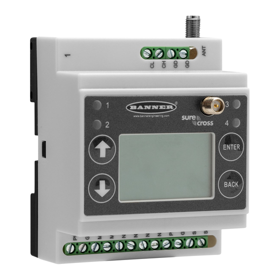
Apply Power to the Controller
Follow these instructions to apply 12–30 V DC power to the controller using a wall plug.
Equipment used:
•
DXM Wireless Controller
•
MQDMC-401 0.3 m (1 ft) cordset with a 4-pin M12/Euro-style quick disconnect fitting
•
PSW-24-1 Wall plug power supply; 24 V DC, 1 A
Important:
•
Never operate a 1 Watt radio without connecting an antenna
•
Operating 1 Watt radios without an antenna connected will damage the radio circuitry.
•
To avoid damaging the radio circuitry, never apply power to a Sure Cross
MultiHop (1 Watt) radio without an antenna connected.
1. Connect the brown wire from the MQDMC-401 cordset to the DXM's PW (+ power) terminal.
2. Connect the blue wire from the MQDMC-401 cordset to the DXM's GD (- ground) terminal.
3. Connect the PSW-24-1 power supply to the MQDMC-401 cordset.
4. Plug in the PSW-24-1 wall plug power supply.
Binding and Conducting a Site Survey with the ISM Radio
The DXM internal ISM radio will either be a MultiHop master radio or a DX80 Gateway radio. Before the ISM radio can
communicate, the ISM radio within the DXM must be bound to the other radios in the wireless network.
Use the DXM LCD menu to bind external radios to the internal ISM radio.
If you are having difficulty running binding or site surveys, it may be because of the speed of the XML configuration file or script
running on the DXM. To resolve this issue, try one of the following options:
•
Disable the XML and script by setting DIP switch 4 on the processor board to ON and cycling the power to the DXM. After
binding the devices, turn DIP switch 4 back OFF and cycle power again to return to normal operation of the XML and
script.
•
Adjust the XML or script to slow down the RTU read or write rules.
•
Upload a blank XML, bind all devices, then upload the configured XML file.
Bind a DX80 Node to a DXM and Assign the Node Address
Before beginning the binding procedure, apply power to all the devices. Separate radios by 2 meters when running the binding
procedure. Put only one DXM Gateway into binding mode at a time to prevent binding to the wrong Gateway.
Binding Nodes to a Gateway ensures the Nodes only exchange data with the Gateway they are bound to. After a Gateway enters
binding mode, the Gateway automatically generates and transmits a unique extended addressing (XADR), or binding, code to all
Nodes within range that are also in binding mode. The extended addressing (binding) code defines the network, and all radios
within a network must use the same code.
1. Enter binding mode on the DXM radio:
a) Use the arrow keys to select the ISM Radio menu on the LCD and press ENTER.
b) Highlight the Binding menu and press ENTER.
2. Assign the Node address to the Node.
•
For Nodes without rotary dials: Use the DXM arrow keys to select the Node address to assign to the DX80 Node about
to enter binding mode. The DXM assigns this Node address to the next Node that enters binding mode. Only bind one
Node at a time.
•
For Nodes with rotary dials: Use the Node's rotary dials to assign a valid decimal Node Address (between 01 and 47).
The left rotary dial represents the tens digit (0 through 4) and the right dial represents the ones digit (0 through 9) of the
Node Address. You can leave the DXM "Bind to" address set to 1 because the Node's rotary dials will override that
setting.
3. Start binding mode on the DXM radio by pressing ENTER on the DXM radio.
4. Enter binding mode on the DX80 Node.
•
For housed radios, triple-click button 2.
•
For board-level radios, triple-click the button.
•
For Nodes without buttons, refer to the Node's datasheet for instructions on entering binding mode.
Original Document
191247 Rev. E
15 October 2020
®
Performance or Sure Cross
191247
Advertisement
Table of Contents

Subscribe to Our Youtube Channel
Related Manuals for Banner DXM


Summary of Contents for Banner DXM
- Page 1 • Disable the XML and script by setting DIP switch 4 on the processor board to ON and cycling the power to the DXM. After binding the devices, turn DIP switch 4 back OFF and cycle power again to return to normal operation of the XML and script.
- Page 2 Before beginning the binding procedure, apply power to all the devices. Separate radios by two (2) meters when running binding procedure. Put only one DXM MultiHop master radio into binding mode at a time to prevent binding the slave radios to the wrong master radio.
- Page 3 There are two ways to set the IP address: using the DXM's LCD menu or using the configuration software to change the XML file. IP addresses entered into the LCD menu system override the IP addresses in the XML configuration files. To use the IP addresses set in the XML configuration file, clear the IP addresses from the menu system.
- Page 4 DXM Controller Quick Start Guide Not all screens are available for all models. To change to another model of DXM, go to the Select Mode screen and use the drop- down list to select another model. If the active configuration is incompatible with the selected model, you will be prompted to either proceed and wipe out the active configuration or cancel the model change and preserve the configuration.
- Page 5 Figure 6. Settings > System > Device Time 1. Go to the Settings > System screen. 2. If you connect the DXM to a computer, click Sync PC Time with Device to set the time on the DXM to match the time of the computer.
- Page 6 Banner Engineering Corp. Limited Warranty Banner Engineering Corp. warrants its products to be free from defects in material and workmanship for one year following the date of shipment. Banner Engineering Corp. will repair or replace, free of charge, any product of its manufacture which, at the time it is returned to the factory, is found to have been defective during the warranty period. This warranty does not cover damage or liability for misuse, abuse, or the improper application or installation of the Banner product.
Need help?
Do you have a question about the DXM and is the answer not in the manual?
Questions and answers