
Related Manuals for Grunbeck desaliQ basic filling module


Summary of Contents for Grunbeck desaliQ basic filling module
- Page 1 We understand water. Heating water treatment system | desaliQ basic filling module Operation manual...
- Page 2 General Contact Germany Phone +49 9074 41-0 Fax +49 9074 41-120 Availability Monday to Thursday 7:00 am - 6:00 pm Friday 7:00 am - 12:00 We reserve the right to technical modifications. © by Grünbeck Wasseraufbereitung GmbH Original operation manual Edition: May 2022 Order no.: 100093940000_en_055...
-
Page 3: Table Of Contents
Table of contents Table of contents Operation/handling ......32 Table of contents ........... 3 Operation of the control unit ....32 Introduction .......... 4 Program selection and sequence ..36 Resetting the water meter ....41 Validity of the manual ......4 Changing the basic settings .... -
Page 4: Introduction
1.1 Validity of the manual This manual applies to the products below: ● desaliQ basic filling module ● desaliQ basic filling module (country-specific version for Switzerland, Denmark and Uruguay) 1.2 Other applicable documents ● Operation manual of mixed bed cartridge desaliQ:MB9 ●... -
Page 5: Product Identification
Introduction 1.3 Product identification You can identify your product based on the product designation and the order no. shown on the type plate. ► Check whether the products given in chapter 1.1 corre- spond to your product. The type plate is located on the device. Item Designation Item... -
Page 6: Symbols Used
Introduction 1.4 Symbols used Symbol Meaning Danger and risk Important information or requirement Useful information or tip Written documentation required Reference to further documents Work that must be carried out by qualified special- ists only Work that must be carried out by qualified electri- cians only Work that must be carried out by technical service personnel only... -
Page 7: Depiction Of Warnings
Introduction 1.5 Depiction of warnings This manual contains information and instructions that you must obey for your personal safety. The information and instructions are highlighted by a warning symbol and are structured as shown below: SIGNAL WORD Type and source of hazard ●... -
Page 8: Demands On Personnel
Introduction 1.6 Demands on personnel During the individual life cycle phases of the product, different people carry out activities on the product. The respective tasks re- quire different skills. 1.6.1 Qualification of personnel Personnel Requirements • Operator/user No special expertise required •... - Page 9 Introduction 1.6.2 Authorisations of personnel The table below specifies which tasks may be carried out by whom. Transport and storage Installation and mounting Start-up Operation and handling Cleaning Inspection Maintenance Troubleshooting Repair Decommissioning and restart/ recommissioning Dismantling and disposal 1.6.3 Personal protective equipment ►...
-
Page 10: For Your Safety
For your safety For your safety 2.1 Safety measures ● Only use genuine spare parts for maintenance or repair. ● Do not make any changes, alterations, extensions or pro- gram changes on your product. ● Risk of slipping due to escaping water. ●... - Page 11 For your safety 2.1.2 Pressure-related hazards ● Components can be under pressure. There is a risk of inju- ries and damage to property due to escaping water and un- expected movement of components. ● Before starting repair and maintenance work, make sure that all affected components are depressurised.
-
Page 12: Product-Specific Safety Instructions
For your safety 2.1.4 Groups of persons requiring protection ● This product is not designed to be used by persons (includ- ing children) with reduced capabilities, lack of experience or lack of knowledge. Unless they are supervised, have been instructed on the safe use of the product and under- stand the resulting hazards. - Page 13 For your safety Before the treatment, check the heating water for quality and possible substances contained such as inhibitors. NOTE Inhibitors contained in the heating circuit ● If inhibitors were added to the heating water, these will be removed by the resin of the softening or mixed bed car- tridge and/or the concentration is reduced during make- up water feed.
-
Page 14: Conduct In Emergencies
For your safety 2.3 Conduct in emergencies 2.3.1 In case of water leaks 1. De-energise the device – pull the mains plug. 2. Close the shut-off valves at the inlet and outlet of the de- vice. 3. Locate the leak. 4. -
Page 15: Product Description
• Mixed bed cartridge desaliQ • Softening cartridge decaliQ 3.1.1 Foreseeable misuse ● The desaliQ basic filling module must not be used for the treatment of raw water that is to be used as drinking water. 15 | 68... -
Page 16: Product Components
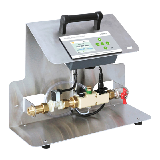
Product description 3.2 Product components Item Designation Item Designation Console Carrying handle Key-operated control panel Cable holder Mains cable with Schuko plug Conductivity sensor Outlet shut-off valve Valve for venting/sampling (pure water) Temperature sensor Turbine water meter (TWZ) Solenoid valve Rubber feet Inlet connection 16 | 68... - Page 17 Product description 3.2.1 Version for Switzerland Instead of the Schuko mains plug, a country-specific mains plug is supplied. Illustration Product Mains plug for Switzerland 3.2.2 Version for Denmark Instead of the Schuko mains plug, a country-specific mains plug is supplied. Illustration Product Mains plug for Denmark...
-
Page 18: Functional Description
Product description 3.3 Functional description The function of the desaliQ basic filling module is based on the well-proven processes of softening or demineralisation. The desaliQ basic filling module works with the following automat- ically monitored operating modes. ● Filling •... -
Page 19: Accessories
Product description 3.4 Accessories Your product can be retrofitted with accessories. Please contact your local Grünbeck representative or Grünbeck’s headquarters in Hoechstaedt/Germany for details. Illustration Product Order no. Hose kit DN 20, straight/straight 707 840 Consisting of: 2 hoses of 1.5 m in length with straight connections, 2 double nipples, including seals Hose kit DN 20, straight/90°... -
Page 20: Transport And Storage
Transport and storage Transport and storage 4.1 Transport ► Transport the product in its original packaging only. ► Do not discard the packaging. Use the packaging for transport between uses. NOTE Residual water in the device after use ● In the event of frost, the remaining, freezing residual wa- ter in the device can damage the components beyond re- pair. -
Page 21: Installation
Installation Installation The work below must be carried out by qualified specialists only. The device must only be connected with flexible connection hoses. Installation example for demineralisation Item Designation Item Designation Drinking water filter Filling section thermaliQ:FB13i Filling adapter Inlet to desaliQ:MB9 Mixed bed cartridge Outlet of desaliQ:MB9 desaliQ:MB9... - Page 22 Installation Installation example for softening Item Designation Item Designation Drinking water filter Filling section thermaliQ:FB13i Filling adapter Inlet to decaliQ cartridge Outlet from decaliQ cartridge Softening cartridge decaliQ Outlet from desaliQ basic fill- ing module to heating circuit 22 | 68...
-
Page 23: Requirements For The Installation Site
Installation 5.1 Requirements for the installation site ● The installation site must be frost-proof and protect the product from direct sunlight, chemicals, dyes, solvents and their vapours. ● The installation room must have a floor drain. If no floor drain is available, an appropriate safety device must be installed. -
Page 24: Checking The Scope Of Supply
(refer to chapter 4) Item Designation Item Designation desaliQ basic filling module Operation manual Seal kit (5x flat seal, 5x sieve seal) ► Check the scope of supply for completeness and damage. 5.3 Water installation Obey the operation manuals below: •... - Page 25 Installation In order to increase the demineralisation or softening capacity, several cartridges can be connected in series. The connection hoses must be selected and laid according to the respective situation on site (refer to chapter 3.4). All connec- tion hoses must be secured against water leaks by means of a seal.
- Page 26 Installation Incorrect installation and routing of the connec- NOTE tion hoses ● Risk of damage due to twisting, contortion, kinking and laying with tensile stress. ► Make sure that the connection hoses are not squeezed, kinked or twisted when connecting them. ►...
- Page 27 1. Mount the connection hose from the filling adapter on the inlet to the cartridge. 2. Mount the connection hose from the cartridge on the inlet of the desaliQ basic filling module. a Insert the sieve seal. 3. Mount the connection hose from the outlet of the desaliQ basic filling module on the filling adapter.
- Page 28 1. Mount the connection hose from the filling adapter on the inlet to the cartridge. 2. Mount the connection hose from the cartridge on the inlet of the desaliQ basic filling module. a Insert the sieve seal. 3. Mount the connection hose from the outlet of the desaliQ basic filling module on the filling adapter.
-
Page 29: Start-Up
Start-up Start-up 6.1.1 Venting the system Item Designation Item Designation Shut-off valve on cartridge Valve for venting/sampling Outlet shut-off valve Valve on connection adapter 1. Open the shut-off valves for drinking water supply. 2. Open the shut-off valve on the cartridge. 3. - Page 30 Start-up Only a system that has been fully vented works without major noise emission. 6.1.2 Checking for leaks ► Visually check all connections on the device and on the entire system for leaks. » No leakage water must escape. 6.1.3 Starting up the product 1.
- Page 31 Start-up Setting the control unit 1. During the initial start-up, set the language and hardness unit in the control unit (refer to chapter 7.1). 2. Obey the instructions given in the control unit. 31 | 68...
-
Page 32: Operation/Handling
Operation/handling Operation/handling Permanent monitoring of the device during operation is not re- quired. The control unit outputs information such as a warning or fault message (refer to chapter 9). 7.1 Operation of the control unit The control unit controls the operation during filling and indicates when interventions are necessary. - Page 33 Operation/handling 7.1.1 Control panel Designation Meaning/Function • To read off the current values Display • Going back Operating • Quitting the menu • Saving a parameter Operating • Aborting or confirming/starting a program step • Setting values • Decreasing the numerical value of a Operating parameter •...
- Page 34 Operation/handling 7.1.2 Display Designation Meaning/Function Home • Basic display for current values Menu display • Green = selectable, inactive level • Orange = active level Menu display Program selection Water meter • Current value Menu display • Resetting the meter Technical service Menu display •...
- Page 35 Operation/handling 7.1.3 Signals Illustration Meaning/Function Information (green) • Program completed successfully Information with exclamation mark (orange) • Program completed; goal not reached, however • Aborting program Warning signal (red) • Program interrupted Fault signal (red) • Program aborted 7.1.4 Basic display Home In the basic display Home, current values are displayed Item Designation...
-
Page 36: Program Selection And Sequence
Operation/handling 7.2 Program selection and sequence ► Select the required operating mode in the menu: ● Filling (refer to chapter 7.2.1). • Demineralisation, Softening ► Obey the instructions in the control unit. The run time of the program depends on the conductivity or hard- ness of the raw water and the capacity of the connected cartridge. - Page 37 Operation/handling 7.2.1 Filling operating modes ► Before carrying out the work, you need to decide whether you want to fill in softened or demineralised water. ● Grünbeck’s recommendation: Use fully demineralised water in combination with thermaliQ safe. Before carrying out the work, the proper cartridge must be in- stalled and prepared.
- Page 38 » The heating circuit is being filled. » The solenoid valve of the desaliQ basic filling module closes automatically as soon as the conductivity limit value is reached. 4. Document the water volume you have made up or have re- quired for filling in the system log of the heating system.
- Page 39 » The heating circuit is being filled. » The solenoid valve of the desaliQ basic filling module closes automatically as soon as the conductivity limit value is reached, or the capacity of the cartridge is exhausted. 5. Document the water volume you have made up or have re- quired for filling in the system log of the heating system.
- Page 40 Operation/handling 7.2.2 Taking samples In order to determine the water hardness, pH value and conduc- tivity, you can use the GENO-therm analysis case (order no. 707 190). 1. Fill the sampling container slowly to prevent the introduc- tion of oxygen into the water sample. 2.
-
Page 41: Resetting The Water Meter
Operation/handling 7.3 Resetting the water meter You can reset the water meter at any time, e.g. after the program has been completed. 1. Select the water meter menu » The current value is displayed. 2. Reset the meter with Yes. 7.4 Changing the basic settings In the code-protected area, you can change the basic settings. -
Page 42: Calibrating The Conductivity Sensor
Operation/handling 7.4.2 Code 245 ► Read the device information: ● Total waste water volume ● Temperature of circuit board 7.4.3 Code 669 ► Reset all values to the factory settings. 7.5 Calibrating the conductivity sensor The work below must be carried out by a qualified specialist only. In Code 121, you can recalibrate the temperature sensor and the conductivity sensor. -
Page 43: Temperature Sensor
Operation/handling ● When tilting the device, the cable may be crushed under the device and damaged. ► When tipping the device over, take care to guide the ca- ble – do not place it under the console. ► Carefully tilt the device on the respective side – use the carrying handle to do so. - Page 44 Operation/handling gefunden werden.Fehler! Verweisquelle konnte nicht gefunden werden.). ► Connect the device to the power supply. ► Enter Code 121 in the technical service menu 7.5.1.1 Calibrating the temperature sensor 1. Measure the room temperature using a reference thermometer. 2. Enter the measured value in the program and confirm the entry.
- Page 45 Operation/handling ► Tilt the device to the left. ► Make sure that the solenoid valve is closed. 1. Fill 1 bottle of calibration solution (50 ml) into the opening of the sensor section – the ball valve must be open. »...
- Page 46 Operation/handling a Make sure the device is vented. 2. Check the conductivity value – it must match the flushing water. » The device is recalibrated. 46 | 68...
-
Page 47: Maintenance And Repair
Maintenance and repair Maintenance and repair Maintenance and repair includes cleaning, inspection and mainte- nance of the product. The responsibility for inspection and maintenance is subject to local and national requirements. The owner/operating company is responsible for compliance with the prescribed maintenance and repair work. -
Page 48: Intervals
Maintenance and repair 8.2 Intervals By way of regular inspections and maintenance, malfunctions can be detected in time and product failures might be pre- vented. The interval table below shows the minimum intervals for the tasks to be carried out. Task Interval Execution... -
Page 49: Inspection
Maintenance and repair 8.3 Inspection You as owner/operating company can do the regular inspections yourself. ► Carry out an inspection at least every 6 months and pro- ceed as follows to do so: 1. Check all water-carrying parts for leaks. 2. - Page 50 Maintenance and repair 8.4.1 Cleaning/calibrating the conductivity sensor ► Proceed as follows to clean the conductivity sensor: Item Designation Item Designation Conductivity sensor Retaining clip 1. Pull out the retaining clip. 2. Pull out the conductivity sensor. 3. Clean the conductivity sensor with drinking water. a Dry the conductivity sensor.
-
Page 51: Spare Parts
Maintenance and repair 8.4.2 Checking the solenoid valve 1. Clean the solenoid valve with a dry cloth. 2. Check the solenoid valve for function. ► Check all electric lines for damage. ► Replace damaged components. 8.5 Spare parts For an overview of the spare parts, refer to our spare parts cata- logue at www.grünbeck.com. -
Page 52: Wearing Parts
Maintenance and repair 8.6 Wearing parts The replacement of wearing parts must be carried out by tech- nical service personnel only. Wearing parts are listed below: ● Seals ● Turbine water meter ● Non-return valve ● Conductivity sensor ● Solenoid valve 52 | 68... -
Page 53: Troubleshooting
Troubleshooting Troubleshooting 9.1 Messages 1. Eliminate the fault (refer to fault table). 2. Acknowledge the fault. 3. Monitor the display of the control unit. 4. If the malfunction reoccurs, compare the display message with the fault table below. Display Explanation Remedy ►... - Page 54 Troubleshooting If a malfunction cannot be eliminated, the technical service per- sonnel or a qualified specialist trained by Grünbeck can take further measures. ► Contact technical service. 54 | 68...
-
Page 55: Decommissioning
Decommissioning 10 Decommissioning Between uses, the desaliQ basic filling module must be taken out of operation and stored temporarily. ► Proceed as follows to take the desaliQ basic filling module out of operation: 2. Flush the device with clear water. -
Page 56: Disposal
Disposal 11 Disposal ► Obey the applicable national regulations. Packaging ► Dispose of the packaging in an environmentally sound manner. Product If this symbol (crossed-out wheelie bin) is on the product, this product or its electrical and electronic components must not be disposed of as household waste. -
Page 57: Technical Specifications
Technical specifications 12 Technical specifications Dimensions and weights Width Depth Height Connection height of sensor section Connection depth of sensor section Approx. weight Connection data Nominal connection diameter of inlet and outlet DN 20 (¾" m. thr.) 230/50 – 60 Power supply V/Hz Rated power (operation) - Page 58 Technical specifications Performance data Nominal pressure 1.5 – 4 Operating pressure (circuit) Flow at Δp 1 bar (in combination with desaliQ:MB9) Nominal flow (in combination with desaliQ:MB9) Flow rate of device General data 5 – 35 Water temperature °C 5 – 40 Ambient temperature °C Order no.
-
Page 59: Operation Log
Operation log 13 Operation log ► Document the initial start-up/commissioning and all maintenance activities. desaliQ basic filling module Serial no.: ___________________ 13.1 Start-up/Commissioning log Customer Name: Address: Installation/Accessories Remarks Start-up Installer/Owner/Operating company: Company: Work time certificate (no.): Date/signature: 59 | 68... -
Page 60: Maintenance
Operation log 13.2 Maintenance Work performed ☐ Inspection ☐ Maintenance ☐ Repair Description Execution confirmed Company: Name: Date: Signature: Work performed ☐ Inspection ☐ Maintenance ☐ Repair Description Execution confirmed Company: Name: Date: Signature: 60 | 68... - Page 61 Operation log Work performed ☐ Inspection ☐ Maintenance ☐ Repair Description Execution confirmed Company: Name: Date: Signature: Work performed ☐ Inspection ☐ Maintenance ☐ Repair Description Execution confirmed Company: Name: Date: Signature: 61 | 68...
- Page 62 Operation log Work performed ☐ Inspection ☐ Maintenance ☐ Repair Description Execution confirmed Company: Name: Date: Signature: Work performed ☐ Inspection ☐ Maintenance ☐ Repair Description Execution confirmed Company: Name: Date: Signature: 62 | 68...
- Page 63 Operation log Work performed ☐ Inspection ☐ Maintenance ☐ Repair Description Execution confirmed Company: Name: Date: Signature: Work performed ☐ Inspection ☐ Maintenance ☐ Repair Description Execution confirmed Company: Name: Date: Signature: 63 | 68...
- Page 64 Operation log Work performed ☐ Inspection ☐ Maintenance ☐ Repair Description Execution confirmed Company: Name: Date: Signature: Work performed ☐ Inspection ☐ Maintenance ☐ Repair Description Execution confirmed Company: Name: Date: Signature: 64 | 68...
- Page 65 Operation log Work performed ☐ Inspection ☐ Maintenance ☐ Repair Description Execution confirmed Company: Name: Date: Signature: Work performed ☐ Inspection ☐ Maintenance ☐ Repair Description Execution confirmed Company: Name: Date: Signature: 65 | 68...
- Page 66 This certificate becomes void if the system is modified in any way not approved by us. Heating water treatment system desaliQ basic filling module Serial no.: Refer to type plate The aforementioned system also complies with directives and provisions below: •...
- Page 68 Grünbeck Wasseraufbereitung GmbH Josef-Grünbeck-Str. 1 89420 Hoechstaedt GERMANY +49 9074 41-0 +49 9074 41-100 info@gruenbeck.com For more information go www.gruenbeck.com to www.gruenbeck.com...
Need help?
Do you have a question about the desaliQ basic filling module and is the answer not in the manual?
Questions and answers