
Subscribe to Our Youtube Channel
Related Manuals for Grunbeck MXA 1 1/4"


Summary of Contents for Grunbeck MXA 1 1/4"
- Page 1 We understand water. Filter | GENO-backwash filter MXA 1"- MXA DN 100 Operation manual...
- Page 2 General Contact Germany International Sales Phone +49 9074 41-145 Technical Service Phone +49 9074 41-333 Fax +49 9074 41-120 Availability Monday to Thursday 7:00 am - 6:00 pm Friday 7:00 am - 4:00 pm Copyright The manufacturer reserves the copyright to this operation manual. Without the written consent of Grünbeck Wasseraufbereitung GmbH, no part of this manual may be reproduced in any way, nor may any part be processed, duplicated or distributed using electronic systems.
-
Page 3: Table Of Contents
Table of contents Table of contents Preparations .............38 About this manual ............. 4 Starting up the product ..........39 Handing over the product to the owner/user ....39 Other applicable documents ........4 Target group .............. 4 Storage of documents ..........4 Operation ..............40 Symbols used ............ -
Page 4: About This Manual
About this manual About this manual Other applicable documents The following documents shall be considered as applicable documents for the GENO backwash filter as well: ● For Grünbeck's technical service/authorised service company: Technical service manual GENO-backwash filter MXA Order no.: TD4-AM001en ●... -
Page 5: Typographical Conventions
About this manual Typographical conventions The following typographical conventions are used in this manual: Designation Depiction Instruction ► Action Single-step instruction or chronological sequence of steps does not matter Instruction 1. First action Multi-step instruction and chronological a first step sequence of steps is important b second step 2. -
Page 6: Type Plate
About this manual Type plate The type plate is located on the front of the filter housing. Please specify the data shown on the type plate in order to speed up the processing of your inquiries or orders. ► Therefore, add the serial number in order to have the necessary data available at all times. -
Page 7: Safety
Safety Safety WARNING: Contamination of drinking water due to improper handling. ● Risk of infectious diseases. ► Have the installation, start-up and annual maintenance carried out by specialist installers only. Safety measures ● Carefully read this manual before operating your product. ●... -
Page 8: Technical Safety Instructions
Safety Technical safety instructions This manual contains information and instructions that you must comply with for your own personal safety as well as to avoid damage to property. The information and instructions are highlighted by a warning triangle and have the following structure: CAUTION: Type and source of danger. -
Page 9: Responsibilities Of The Owner/User
Safety ● Inform the owner/user about possible dangers that can arise during the operation of the product. ● Fill in the operation log (refer to chapter 12). Responsibilities of the owner/user Comply with the following instructions to ensure the proper and safe functioning of the product: ●... -
Page 10: Product Description
Product description Product description Intended use ● GENO-backwash filters MXA are designed for the filtration of drinking and industrial water. ● The filters are suitable for the filtration of process, boiler feed, cooling and air conditioning water – only in partial flow. ●... -
Page 11: Product Components
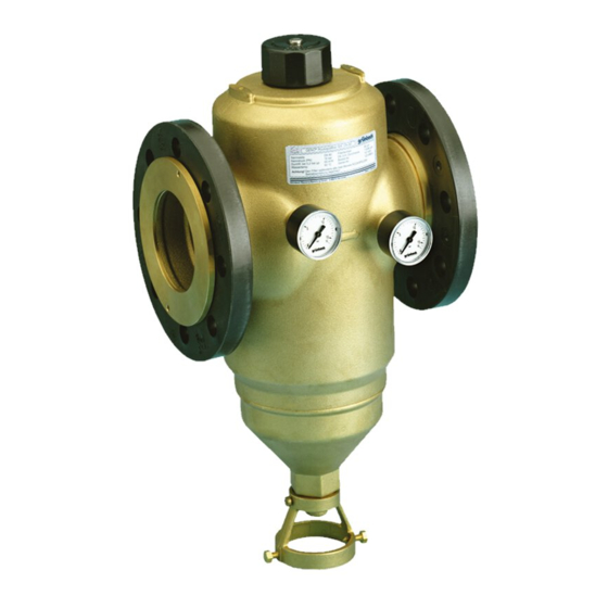
Product description Product components Item Designation Item Designation Shock-proof plug, 1.5 m cable Differential pressure sensor Cover Water meter screw connection Filter housing Pressure gauge Brush Sieve bottom Suction nozzle Filter element Gasket Filter funnel Backwash water connection Flange connection Control unit GENO-RS-tronic 11 | 72... -
Page 12: Functional Description
Product description Functional description The unfiltered raw water flows into the filter from the inlet side and then from the inside out through the filter element and to the pure water outlet. Thus, foreign particles of a size > 100 µm are retained. Depending on their size and weight, the foreign particles stick to the filter element or they fall straight down into the filter funnel. - Page 13 Product description 3.4.1 Backwash with the GENO-RS-tronic control unit The GENO-RS-tronic control unit activates time and differential pressure controlled backwash processes. Apart from a time interval for the activation of a backwash, an off-period during which no backwash processes may take place can also be defined. An actuator opens the backwash water outlet.
-
Page 14: Accessories
Product description Accessories You can retrofit your product with additional accessories. Please contact your local Grünbeck representative or Grünbeck’s headquarters in Hoechstaedt for more details (refer to www.gruenbeck.com). Designation Order no. 1" / 1¼" 1½" / 2" / DN 65 DN 80 / DN 100 50 µm filter element 107 052... -
Page 15: Installation
Installation Installation The installation of a filter represents a major intervention into the drinking water system and may only be performed by a specialist installer. In accordance with DIN EN 806-2 and DIN EN 1717, the product is installed in the water pipe downstream of the water meter and upstream of distribution pipes or the systems to be protected. - Page 16 Installation GENO-backwash filter MXA with screw connections GENO-backwash filter MXA with flange connections Item Designation Item Designation Inlet shut-off valve Outlet shut-off valve 16 | 72...
-
Page 17: Requirements Regarding The Installation Site
Installation Requirements regarding the installation site Observe local installation directives, general guidelines and technical specifications. ● The installation site must be frost-proof and ensure the filter's protection from chemicals, dyes, solvents, vapours and direct sunlight. ● A drain connection (DN 50) must be available to discharge the backwash water. ●... -
Page 18: Checking The Scope Of Supply
Installation Checking the scope of supply Item Designation Item Designation Control unit GENO-RS-tronic Water meter screw connection with gasket, union nut Filter with screw connections Backwash water connection Operation manual Filter with flange connections The filter is available with screw connections for sizes: 1" (DN 25), 1¼" (DN 32), 1½"... -
Page 19: Installing The Product
Installation Installing the product Only install the GENO-backwash filter MXA horizontally and without mechanical stress. Please note the following points before installation: ● Installation only possible in horizontal position ● Free outlet and discharge of the backwash water without backpressure 4.4.1 Changing the direction of flow ►... - Page 20 Installation 4.4.2 Installing the GENO-backwash filter MXA with screw connections 1. Install the pipe fitting into the pipe (the installation dimension must be: 190 mm for sizes 1", 1¼" and 206 mm for sizes 1½", 2"). 2. Position the filter (note the marking for the flow direction on the filter). 3.
- Page 21 Installation 4.4.3 Installing the GENO-backwash filter MXA with flange connection 1. Prepare the pipe with flange connection in accordance with DIN EN 1092-1 (the distance between the two gaskets must be: 220 mm for DN 65 and 250 mm for DN 80 and DN 100).
- Page 22 Installation 4.4.4 Installing the backwash water connection CAUTION: Splashing hot water at the drain outlet during backwash. ● Danger of scalding in case of hot water filtration without waste water pipe. ► For hot water filtration, install a fixed waste water pipe at the drain connection. If it is not possible to install a waste water pipe, the backwash water can be collected in a bucket/container.
- Page 23 Installation 5. Install a waste water pipe towards the drain connection. » The backwash water connection is installed. The drain connection is available as an option (refer to Accessories, chapter To install the drain connection, follow the mounting instructions TD5-BS002. 23 | 72...
- Page 24 Installation 4.4.5 Electrical installation DANGER! Live components! ● Risk of electric shock when working on the electrical system. ► Make sure that the mains voltage is disconnected and that the plug is unplugged. ► Do not connect to mains until the connection work has been completed and the control unit is closed.
- Page 25 Installation Fastening the control unit The control unit must not be installed in the immediate vicinity of heat sources with high radiation temperatures. ► Fasten the control unit on the wall. NOTE: Securely fasten the control unit. ● Precarious and unsound fastening can cause the control unit to crash. ►...
- Page 26 Installation Wiring diagram of the control unit Wiring diagram of GENO-backwash filter MXA Item Designation Item Designation Safety solenoid valve Connecting line to filter Backwash valve Open Brown Backwash valve Closed Motor, 24 V~ Blue Ext. input Black Illuminated LED: Voltage supply, cam-operated Safety device solenoid valve, 24 V ~, switch, programmable input and differential pressure order no.
- Page 27 Installation 4.4.6 Additional inputs and outputs Activation of backwash at external input In addition to the general electrical wiring, you can install the control unit for external activation of the backwash. ► Connect the connecting line at the external input E, terminals 17 and 18. This control unit input is designed for wiring with a voltage-free contact.
-
Page 28: Control Unit Geno-Rs-Tronic
Control unit GENO-RS-tronic Control unit GENO-RS-tronic Components of the control unit Item Designation Item Designation Shock-proof plug, 1.5 m cable Cover Operating / Menu level Release button Connection level NOTE: Incorrect setting/operation of the control unit ● Dangerous operating conditions/functional impairments may occur - health/personal/property damage possible ►... - Page 29 Control unit GENO-RS-tronic 5.1.1 Releasing a backwash With the GENO-RS-tronic, a backwash can be activated in: 1. Automatic release by time interval ● The time interval is adjustable from 1 hour - 99 days. ● The time interval is generally active. ●...
-
Page 30: Overview Of Display
Control unit GENO-RS-tronic Overview of display Item Designation Item Designation Display Connection data of the control unit Button I for information Button R for backwash Explanation of manual backwash Button P for program Explanation of symbols displayed 30 | 72... - Page 31 Control unit GENO-RS-tronic 5.2.1 Display indication First line Illustration Explanation Wrench • Displayed with error messages • If the maintenance interval has elapsed or when more backwash processes were carried out per maintenance interval than permitted. Clock Indicates an interval-controlled backwash: •...
- Page 32 Control unit GENO-RS-tronic Second line Standard operation ● Indicates the time (basic display) Information menu level ● Indicates the operating parameters User menu level ● Indicates the numerical value of the parameter in the menu • Open parameters are flashing Parameter number (small figure) ●...
-
Page 33: Navigating The Control Unit
Control unit GENO-RS-tronic Navigating the control unit ► Press the release button on the side. » The cover of the control unit is unlocked and can be opened. 5.3.1 Buttons Illustration Designation Function In standard mode: Program ● Switches to User menu level. Button P In the User menu level: ●... - Page 34 Control unit GENO-RS-tronic 5.3.2 Selecting menu levels Objective Step Status level ► Press the buttons at the same time. Information level ► Press the button in the status level 1x - 6x, rotating through the display and back to the basic display. User menu level ►...
- Page 35 Control unit GENO-RS-tronic 5.3.3 Setting the parameters Objective Step Selecting parameters In every menu level, the button switches to the next parameter and the button switches to the previous parameter. Opening When the desired parameter is displayed: parameters ► Press the button.
-
Page 36: Menu Structure
Control unit GENO-RS-tronic Menu structure Menu level Menu items Values/settings Status level Acknowledgement of Press one of the three buttons. malfunctions Manual backwash Press the button for more than 5 s Select the menu Refer to chapter 5.3.2 level Information Current configuration of the backwash. - Page 37 Control unit GENO-RS-tronic If the backwash lock is activated, a backwash is performed automatically 5 min before the start and after the end of the backwash lock. A minimum of 1 hour must be scheduled between the start and the end of a backwash lock. The interval-controlled backwash must be scheduled at a time outside of an active backwash lock.
-
Page 38: Start-Up
Start-up Start-up Preparations NOTE: Upon delivery, the drain outlet of the GENO-backwash filters MXA is open. ► Close the open drain outlet for 1.5 min: 1. Press and hold the button. 2. Plug the mains plug into the socket. 3. Release the button. -
Page 39: Starting Up The Product
Start-up Starting up the product ► Carry out the following steps after installation and after every maintenance. 1. Set the time (refer to chapter 7.2.1). 2. Set other operating parameters, if necessary (refer to chapter 7.2). 3. Open the shut-off valves. 4. -
Page 40: Operation
Operation Operation Information in the basic display Status level The display continuously gives information on the operating state of the system. Indicating parameters in the basic display: ● Functions that are activated to trigger a backwash. ● Function by which the current backwash was triggered. ●... -
Page 41: Setting Parameters In The User Level
Operation Button pressed Indication Explanation Go to 5x if backwash lock function is deactivated XX:XX Start time of backwash lock YY:YY End time of backwash lock XX:YY Number of microswitch pulses during the last backwash process. The displayed value is only updated during the ongoing backwash Upon opening, factory setting 36 Upon closing, factory setting 34...40... -
Page 42: Setting Parameters In The Programming Level
Operation 4. Press the button to switch to the display for minutes. 5. Press the button to open the parameter for the minutes. » The display for minutes flashes. 6. Press the or the button to set desired value. 7. Press the button to save the setting. - Page 43 Operation 7.3.1 Entering the Code ► Press the buttons in the status level for more than 1 s. » The display switches from the time to the three flashing digits “000” and the parameter no. switches to “C”. 1. Press the or the button to select code 113.
- Page 44 Operation 7.3.3 Setting the backwash interval The example below shows you how to work in the programming level/code-protected level. The interval-controlled backwash is always active and set to 30 d in the factory setting. You can choose between two configurations: Period Range Explanation...
- Page 45 Operation 7. Press the or the button to set the desired value of the parameter. 8. Press the button to save the value. » The value of the parameter stops flashing. » The hours are set. ► Press the and the button at the same time to return to the status level (basic display).
-
Page 46: Cleaning, Inspection, Maintenance
Cleaning, inspection, maintenance Cleaning, inspection, maintenance WARNING: Danger of contaminated drinking water if the work is not carried out properly. ● Risk of infectious diseases. ► Pay attention to hygiene when working on the installation. Inspection and maintenance of a filter is prescribed in the DIN EN 806-5 standard. Regular maintenance ensures trouble-free and hygienic operation. -
Page 47: Intervals
Cleaning, inspection, maintenance Intervals Task Interval Execution Inspection 2 months Visual/functional check Maintenance 6 months Manual backwash Annually Check O-rings, flat gaskets and brush for wear and tear, check tight fit, backwash Maintenance 5 years Recommended: changing filter element, gaskets, suction nozzle unit Inspection According to DIN EN 806-5, the owner/user must inspect the filters every 2 months. -
Page 48: Maintenance
Cleaning, inspection, maintenance Maintenance WARNING: Non-regular backwash of the filter element ● Health risk due to contamination of the drinking water. ► Observe the intervals for inspection and backwash of the filter element. 8.4.1 Semi-annual maintenance Manual backwash of the filter During the backwash process, filtered pure water is still available. - Page 49 Cleaning, inspection, maintenance If the raw water is heavily contaminated, the standard backwash water outlet can be increased from Ø 6.5 mm to max. Ø 7.5 mm. This increases the cleaning effect and the amount of backwash water per backwash. This measure may only be carried out by a specialist installer.
- Page 50 Cleaning, inspection, maintenance Opening and checking the filter 1. Close the inlet and outlet shut-off valves. 2. Initiate a manual backwash. » Backwash water exits via the drain valve. 3. Disconnect the system’s mains plug after 5 s. » The suction nozzle stops in its position and the water can flow out of the filter. 4.
- Page 51 Cleaning, inspection, maintenance 9. Remove the filter element. 10. Check the filter element for impurities and damage. 11. Check the O-rings of the filter element (outside and inside) for wear and tear. Depending on the filter size, different filter elements are combined. If one filter element is damaged, you can either replace one filter element or a complete set of filter elements.
- Page 52 Cleaning, inspection, maintenance Closing the filter 1. Fit the O-rings to the filter elements. Slide the filter elements with the larger Ø pointing forward over the suction nozzle into the housing of the filter. 2. Position the sieve bottom between the pipe nozzle and the lower suction nozzle. 3.
-
Page 53: Spare Parts
Cleaning, inspection, maintenance Spare parts For spare parts and consumables please contact your local Grünbeck representation which you can find on the internet at www.gruenbeck.de/Service/Ersatzteilkatalog. Use of filter elements with pore sizes: 50 µm, 200 µm and 500 µm only after consultation with Grünbeck Wasseraufbereitung GmbH –... -
Page 54: Troubleshooting
Troubleshooting Troubleshooting WARNING: Risk of contaminated drinking water due to unintentional, significant reduction in pressure. ● Risk of infectious diseases. ► Remedy this malfunction immediately. ► If you cannot remedy malfunctions with the instructions given below, contact Grünbeck's technical service/authorised service company. ►... - Page 55 Troubleshooting Troubleshooting Explanation/Cause of error Troubleshooting Er 1 Control unit does not receive enough Contact the specialist pulses from the microswitch installer or Grünbeck's technical service. Motor blocked or defective If water leaks from the drain Mechanical connection between motor opening, close the filter and pipe nozzle sheared off manually.
- Page 56 Troubleshooting Troubleshooting Explanation/Cause of error Troubleshooting Maintenance interval has elapsed or Contact the specialist installer Er 4 permissible number of backwash or Grünbeck's technical processes per maintenance interval service. has been exceeded Differential pressure sensor or its Contact the specialist installer Er 5 connection line defective or Grünbeck's technical...
-
Page 57: Other Malfunctions
Troubleshooting Other malfunctions Explanation/Cause of Troubleshooting error Troubleshooting No indication, motor does System fuse blown Replace the T2A fuse (micro- not rotate any longer fuse, nominal value 2A, characteristic “slow-blow”). (For position of the fuse refer to chapter 4.4.5 – „Wiring diagram of control unit“) Green lamp above Wiring error... - Page 58 Troubleshooting Explanation/Cause of Troubleshooting error Troubleshooting Water leaks from the lower A particle got stuck Carry out several backwash drain outlet, backwash between the lower suction processes. filter cannot be closed by nozzle and the filter funnel If water continues to escape, means of the control unit Mechanical blockage in the check the filter for foreign...
-
Page 59: Manually Closing The Filter's Suction Nozzle
Troubleshooting Manually closing the filter’s suction nozzle Due to malfunctions, it may be necessary to close the filter’s suction nozzle manually to avoid unnecessary water leakage. To do so, you will need the following: ● Open-ended wrench (SW11) or ● Flat-head screwdriver Proceed as follows: 1. - Page 60 Troubleshooting 3. Loosen the nuts of the cover. 4. Lift the cover of the filter housing. 5. Disconnect the cables of the microswitch. » You can now dismount the motor. 6. Lift the motor unit off the filter housing. 60 | 72...
- Page 61 Troubleshooting 7. Loosen the nut. 8. Remove nut and cam disc. 9. Using an open-ended wrench or a screwdriver, turn the wrench flat of the pipe nozzle to the left until the mechanical stop is reached. » The suction nozzle is closed manually. 10.
-
Page 62: Disposal
Disposal Disposal Comply with the applicable national regulations. 10.1 Packaging Dispose of the packaging in an environmentally sound manner. Dispose of the filling material (foam) as non-recyclable waste. 10.2 Product If this symbol (crossed out waste bin) is on the product, this product is subject to the European Directive 2012/19/EU. -
Page 63: Technical Specifications
Technical specifications Technical specifications Dimensions and weights GENO-backwash filter MXA with screw connections Nominal connection diameter DN 25 DN 32 DN 40 DN 50 1¼“ Connection diameter 1" 1½" 2" Installation length without screw [mm] connection Installation length with screw connection [mm] Min. - Page 64 Technical specifications Dimensions and weights GENO-backwash filter MXA with flange connection Nominal connection diameter DN 65 DN 80 DN 100 Installation length without counter-flanges; [mm] flanges PN 16 acc. to DIN EN 1092-1 Min. distance to wall [mm] Overall height above centre of connection [mm] Overall height up to centre of connection [mm]...
-
Page 65: Pressure Loss Curves
Technical specifications 11.1 Pressure loss curves Pressure loss curves of GENO-backwash filters MXA 1" and 1¼" Item Designation Item Designation Pressure difference [bar] Flow rate [m Pressure loss curves of GENO backwash filters MXA 1½" and 2" Item Designation Item Designation Pressure difference [bar] Flow rate [m... - Page 66 Technical specifications Pressure loss curves of GENO backwash filters MXA DN 65, DN 80 and DN 100 Item Designation Item Designation Pressure difference [bar] Flow rate [m Consumption data Backwash water volume at a water pressure of 3 bar and a backwash time of 1.5 min, approx.
-
Page 67: Operation Log
Operation log Operation log Filter | GENO-backwash filter MXA ____________ Serial no.: ________________________________ 12.1 Start-up log Customer Name: Address: Installation/Accessories Drain connection acc. to DIN EN 1717: Floor drain available: Safety device: Operating values Water pressure at raw water inlet [bar] Water pressure downstream of [bar]... -
Page 68: Maintenance
Operation log 12.2 Maintenance Date Work performed Signature 68 | 72... -
Page 69: Eu Declaration Of Conformity
EU Declaration of Conformity EU Declaration of Conformity In accordance with the EU Low-Voltage Directive 2014/35/EU, Appendix IV This is to certify that the system designated below meets the safety and health requirements of the applicable European guidelines in terms of its design, construction and execution. If the system is modified in a way not approved by us, this certificate is void. -
Page 70: Index
Index Index Accessories ............... 14 Menu structure ..............36 Messages on the display ........... 54 Mounting MXA with flange connection....... 21 Mounting MXA with screw connections ......20 Backwash ................39 Basic display of GENO-RS-tronic ........40 Operation log ..............67 Operator level .............. - Page 72 Grünbeck Wasseraufbereitung GmbH Josef-Grünbeck-Str. 1 89420 Hoechstaedt/Germany +49 9074 41-0 +49 9074 41-100 info@gruenbeck.com For more information go www.gruenbeck.com to www.gruenbeck.com...
Need help?
Do you have a question about the MXA 1 1/4" and is the answer not in the manual?
Questions and answers