Table of Contents
Advertisement
Quick Links
Advertisement
Table of Contents

Related Manuals for Grunbeck osmoliQ:LB


Summary of Contents for Grunbeck osmoliQ:LB
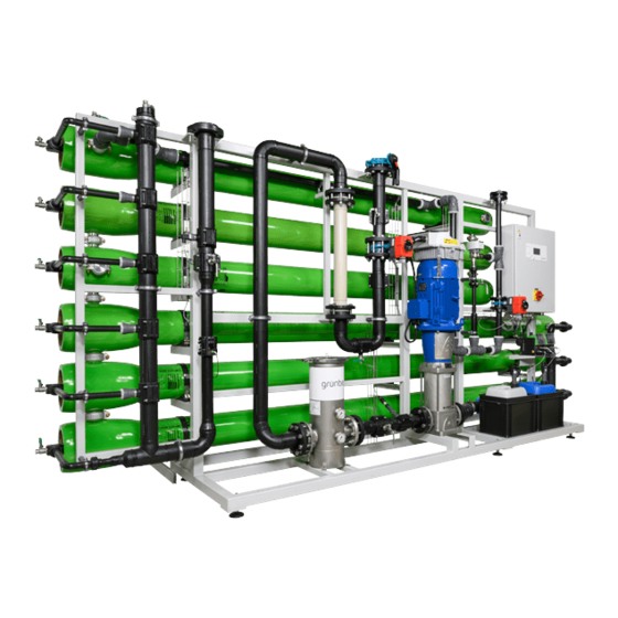
- Page 1 We understand water. Reverse osmosis system | osmoliQ:LB Operation manual...
- Page 2 General Contact Germany International Sales +49 9074 41-145 Service +49 9074 41-333 service@gruenbeck.de Availability Monday to Thursday 7:00 am - 6:00 pm Friday 7:00 am - 4:00 pm We reserve the right to technical modifications. © by Grünbeck Wasseraufbereitung GmbH Original operation manual Edition: March 2023 Order no.: 100066090000_en_034...
-
Page 3: Table Of Contents
Table of contents Table of contents Start-up of antiscalant dosing system (option) ..52 Table of contents ..............3 Handing over the product to the owner/operator/operating company ......53 Introduction ............... 4 Validity of the manual ..........4 Operation ..............54 Other applicable documents ........4 Product identification .......... -
Page 4: Introduction
Introduction Introduction This manual is intended for owners/operators/operating companies, users as well as qualified specialists and ensures the safe and efficient handling of the product. The manual is an integral part of the product. ► Carefully read this manual and the included manuals on the components before you operate your product. -
Page 5: Product Identification
Introduction Product identification You can identify your product based on the product designation and the order no. indicated on the type plate. ► Check whether the products indicated in chapter 1.1 correspond to your product. Designation Designation CE mark Power supply Obey the operation manual Ambient temperature Disposal information... -
Page 6: Depiction Of Warnings
Introduction Symbol Meaning Reference to further documents Work that must be carried out by qualified specialists only Work that must be carried out by qualified electricians only Work that must be carried out by technical service personnel only Depiction of warnings This manual contains information and instructions that you must obey for your personal safety. - Page 7 Introduction 1.6.1 Qualification of personnel Personnel Requirements • No special expertise required User • Knowledge of the tasks assigned • Knowledge of possible dangers in case of incorrect behaviour • Knowledge of necessary protective equipment and protective measures • Knowledge of residual risks •...
- Page 8 Introduction 1.6.3 Personal protective equipment ► As an owner/operator/operating company, make sure that the required personal protective equipment is available. The components below fall under the heading of personal protective equipment (PPE): Protective gloves Protective footwear Protective overall Safety goggles Hard hat Mask Face shield...
-
Page 9: Safety
Safety Safety Safety measures ● Only operate your product if all components are installed properly. ● Obey the local regulations on drinking water protection, accident prevention and occupational safety. ● Do not make any changes, alterations, extensions or program changes on your product. - Page 10 Safety Before starting work on active system parts, make sure they are de-energised. Make sure they stay de-energised for the duration of the work. Obey the 5 safety rules below: a Disconnect (unplug the power plug) b Secure against restart c Verify that no voltage is present d Ground and short-circuit e Cover or block off adjacent live parts...
-
Page 11: System-Specific Safety Instructions
Safety Cleaning/Disposal ● Immediately absorb leaked chemicals with suitable binding agents. ● Collect and dispose of chemicals in such a way that they cannot pose a risk to people, animals, or the environment. 2.1.5 Groups of persons requiring protection ● Children must not play with the product. ●... -
Page 12: Conduct In Emergencies
Safety 2.2.2 Signals and warning mechanisms at the system Warnings/pictograms Risk of electric shock (attached to distributor cover and in the power distributor/switch cabinet) ► Disconnect the system from the power supply before working on electrical system parts Risk of electric shock due to residual voltage (attached to frequency converter) ►... -
Page 13: Product Description
Product description Product description Intended use The reverse osmosis system osmoliQ:LB is designed for the demineralisation of raw water whose composition complies with the quality requirements of the German Drinking Water Ordinance (TrinkwV). 3.1.1 Application limits We assume that the composition of the feed water will not change significantly, that the feed water will always be free of mechanical and organic impurities and that the limit values indicated below will not be exceeded. -
Page 14: Product Components
Product description Product components Designation Functions/characteristics Coding Permeate vent valve Venting of permeate collection pipe RO1H54 Sampling valve Sampling valve to withdraw total permeate RO1H52 Total permeate Permeate conductivity Conductivity sensor for continuous measurement of the RO1CQ1 permeate conductivity – display of the measured value in measuring cell the control unit Feed water shut-off valve... - Page 15 Product description Designation Functions/characteristics Coding – Aluminium rack Rack made of aluminium to house the system components, piping and switch cabinet, with levelling feet to compensate for uneven floors Pressure gauge Indication of operating pressure RO1CP4 Operating pressure Motor control valve For automatic control of the necessary volume flow RO1V2 Concentrate recirculation...
-
Page 16: System Connections
The remaining concentrate is captured by a flow meter and directed to the drain via an automatic control. Using the existing feed water pressure, the remaining constituents are flushed from the osmoliQ:LB via an additional automatic fitting after each operating period (permeate tank full). 16 | 104... - Page 17 Product description 3.4.1 Process/function The pre-treated feed water flows in parallel over the surface of the membrane. The water recirculated within the system is called FEED. A partial flow of pure water passes through the membrane as permeate (cross flow), while the remaining partial flow –...
- Page 18 Product description RO process Reverse osmosis is reversing the natural osmosis process. Water (diluted solution) Concentrated solution Membrane Osmosis Explanation Osmosis occurs when two solutions of different concentrations of dissolved minerals are separated from each other by a membrane. Water passes from the diluted solution (A) through the semi- permeable membrane (C) to the concentrated solution (B) until the concentration is balanced on both sides of the membrane.
-
Page 19: Accessories
Product description Accessories You can retrofit your product with accessories. Please contact your local Grünbeck representative or Grünbeck’s headquarters in Hoechstaedt/Germany for details. Illustration Product Order no. Fine filter BOXER KX 1" 101 835 80 µm filter element for prefiltration Fine filter BOXER KDX 1"... - Page 20 Product description Illustration Product Order no. Communication module PROFIBUS DP 750 160 For connection to a PROFIBUS DP master. Communication module BACnet-IP 750 170 For connection to a BACnet-IP master. Communication module Modbus RTU 750 175 For connection to a Modbus RTU master. Voltage-free signals 750 180 For connection to a Building Management System/Central Control Station.
-
Page 21: Transport, Set-Up And Storage
Transport, set-up and storage Transport, set-up and storage Shipping/Delivery/Packaging The system is fixed on a pallet at the factory and secured against tipping. ► Upon receipt, immediately check for completeness and transport damage. ► In case of visible transport damage, proceed as follows: •... -
Page 22: Transport/Set-Up
Transport, set-up and storage Transport/Set-up WARNING Improper transport ● The system’s centre of gravity is top-heavy. The system can tip and crush persons/limbs. ► Transport the system by means of a forklift or lift truck with appropriate forks only. ► Do not transport the system over inclines or stairs. ►... -
Page 23: Installation
Installation Installation The installation of the system represents a major intervention into the drinking water system and must be carried out by a qualified specialist only. Installation example osmoliQ:LB4000 Designation Designation Fine filter (e.g. BOXER KX) Hardness control measuring device softwatch System separator GENO-DK-2 1½"... -
Page 24: Requirements For The Installation Site
Installation Requirements for the installation site Obey the local installation directives, general guidelines and technical specifications. ● The installation site must be frost-proof and ensure the system's protection from chemicals, dyes, solvents, and their vapours. ● Avoid strong heat radiation and direct sunlight. ●... - Page 25 Installation 5.1.2 Products installed upstream ● The components below must be installed upstream of the system: • Fine filter • Euro system separator • Activated carbon filter or liquid dosing to reduce oxidants • Water softener or antiscalant dosing system ●...
-
Page 26: Water Installation
Installation 5.1.3 Requirements for electrical wiring ● For the power supply of the system, a power outlet 3x 400 V/50 Hz/3 phases/N/PE must be provided by the client on site. ● The supply line to the system provided by client on site must be dimensioned and routed according to the respective type of system –... -
Page 27: Electrical Installation
Installation 1. Install a flushing adapter each in the “feed water” inlet pipe and the “permeate” outlet pipe. 2. Connect the inlet pipe to the “feed water” connection. 3. Connect the outlet pipe to the “concentrate-to-drain” connection according to DIN EN 1717 (with free outlet). - Page 28 Installation NOTE Operation of the high-pressure pump/the frequency converter ● The frequency converter of the high-pressure pump can cause malfunctions of the residual current circuit breaker installed in the mains supply line. ► Use an AC/DC sensitive RCCB with a response threshold of 300 mA. ►...
- Page 29 Installation 5.3.2 Establishing the electrical connection 4. Open the switch cabinet. 5. Establish the power supply – refer to the electric circuit diagram (project-specific). 5.3.3 Line connections (within the GENO-tronic control unit) WARNING External voltage possible at voltage-free contacts and on the circuit board ●...
- Page 30 Installation Operating board Designation Designation RS-485 for interconnection of Modbus RTU Anybus module interface RS-485 for interconnection of Modbus RTU Voltage supply USB 2.0 reserve RS-485 basic module Ethernet 10/100 Mbit RS-485 for interconnection of internal system components SD card slot Terminating resistors for RS-485 interfaces Terminal strip of main circuit board Designation...
- Page 31 Installation Fuses of main circuit board Fuse Function Comments 2 A slow-blow Main fuse of mains input 0.63 A slow-blow 24 VDC solenoid valves, step motors 0.5 A slow-blow Operating board 24 VDC For other connections of the main circuit board, refer to the electric circuit diagram. Interface RS-485 Data line to interconnected subsystems Water softener and/or Pressure booster Connecting terminating resistors...
-
Page 32: Connection/Settings Of Communication Interface Modbus Rtu
Installation Connection/Settings of communication interface MODBUS RTU The RS-485 connector plug is accessible upon opening the door of the switch cabinet. 5.4.1.1 Configuration of the 3-pin connector Terminal Designation A (+) B (-) GNDS1 5.4.1.2 Settings The Modbus RTU address is set at the GENO-tronic control unit (module address). You can change the values below: ●... - Page 33 Installation Logon of interface modules Modbus RTU Module address 33 | 104...
- Page 34 Installation 5.4.3 Data from master to communication module MODBUS Modbus Bytes Value Format Resolution Factor Function/Comment Register System state RO system bool Off/On With this bit, you can switch the system on or off. bool bool bool bool bool bool bool Actuation bool...
- Page 35 Installation Modbus Bytes Value Format Resolution Factor Function/Comment Register Manual regeneration of water softener bool Off/Start With this bit, you can start the manual regeneration. Triple regeneration of water softener (Delta– p) bool With this bit, you can start the triple regeneration. bool bool bool...
- Page 36 Installation Modbus Bytes Value Format Resolution Factor Function/Comment Register 0…65535 Counter Run time of dosing value pump RO1P2 0…65535 Counter Run time Dosing value pump RO1P3 0…9,999,999.9 ³ Counter Sum Permeate Dint value 0…9,999,999 Counter m³ Sum Concentrate-to- Dint value drain 0…9,999,999 Counter...
- Page 37 Installation Modbus Bytes Value Format Resolution Factor Function/Comment Register Normal/ Forced flushing signal This bit indicates when bool the system is in forced flushing. Normal/ Forced stop signal This bit indicates when bool the system is in forced stop. Normal/ No general warnings signal pending...
- Page 38 Installation Modbus Bytes Value Format Resolution Factor Function/Comment Register bool Closed/ Solenoid valve Open Discharge of permeate RO1V4 This bit indicates when the valve for the discharge of permeate RO1V4 is open. bool Closed/ Blending solenoid Open valve RO1V5 This bit indicates when the blending solenoid valve RO1V5 is open.
- Page 39 Installation Modbus Bytes Value Format Resolution Factor Function/Comment Register bool Normal/ Fault Recovery Fault This bit indicates when the recovery too high. bool Normal/ Fault Membrane cross Fault flow This bit indicates when the cross flow deviates. bool Normal/ Fault Permeate Fault conductivity RO1CQ1 This bit indicates when...
- Page 40 Installation Modbus Bytes Value Format Resolution Factor Function/Comment Register bool Normal/ Fault Conductivity Fault measurement RO1CQ1 This bit indicates when the conductivity is exceeded. bool Normal/ Fault Programmable Fault input This bit indicates when a freely programmable fault is present. bool Normal/ Fault Permeate water...
- Page 41 Installation Modbus Bytes Value Format Resolution Factor Function/Comment Register Counter Operating hours value DEA1P2 Counter Sum Flow rate 0…99999 Dint m³ value DEA1CF1 Measuring Remaining time of 0…999 value maintenance interval bool Normal/ Fault pressure booster Fault DEA1P1 This bit indicates when a fault is present at the pressure booster pump.
- Page 42 Installation Modbus Bytes Value Format Resolution Factor Function/Comment Register bool Normal/ Power failure signal This bit indicates when there was a power failure. bool Normal/ No bus connection to signal OSMO-X This bit indicates that the systems are not connected. Operating mode “Bus”...
- Page 43 Installation Modbus Bytes Value Format Resolution Factor Function/Comment Register bool Normal/ Washing out signal This bit indicates when the system is in step Washing out. bool Normal/ Regeneration running signal This bit indicates when the system is in regeneration. bool Normal/ Exchanger operation signal...
- Page 44 Installation Modbus Bytes Value Format Resolution Factor Function/Comment Register bool Normal/ Fault Water meter Fault Exchanger EX1 Er -8 This bit indicates when there was a power failure. bool Normal/ Fault Water meter Fault Exchanger EX2 Er -8 This bit indicates when there was a power failure.
- Page 45 Installation 5.4.4.5 Signals of water softener WE-X Modbus Bytes Value Format Resolution Factor Function/Comment Register Measuring Residual capacity 0…999.9 m³ value Exchanger NX1B1 Measuring Residual capacity 0…999.9 m³ value Exchanger NX1B2 Measuring Flow rate Exchanger 99.9 m³/h value NX1CF1 Regeneration counter Counter 0…99999 Dint...
- Page 46 Installation Modbus Bytes Value Format Resolution Factor Function/Comment Register bool Normal/ 1 = Maintenance interval Fault expired This bit indicates when the maintenance interval has expired. bool Normal/ Reserve Fault bool Normal/ Reserve Fault bool Normal/ Reserve Fault bool Normal/ Reserve Fault bool...
- Page 47 Installation Modbus Bytes Value Format Resolution Factor Function/Comment Register bool Reserve Reserve bool Reserve Reserve bool Reserve Reserve bool Reserve Reserve bool Reserve Reserve bool Reserve Reserve bool Reserve Reserve Water bool Reserve Reserve softener bool Reserve Reserve WE-X bool Reserve Reserve bool...
-
Page 48: Start-Up/Commissioning
Start-up/commissioning Start-up/commissioning The initial start-up of the system must be carried out by technical service personnel only. Climbing onto system components when operating components that are CAUTION located at high levels. ● Risk of falling when climbing onto system components ●... - Page 49 Start-up/commissioning WARNING Contact with preserving agent ● Eye/skin burns. ► Use personal protective equipment (PPE). ► Obey the safety data sheet of the chemical. NOTE Skipping or prematurely terminating the flushing process ● By flushing out the preserving agent, the system is vented at the same time. ●...
- Page 50 Start-up/commissioning NOTE Damage to the system when operated with hard water ● Operating the system with hard water results in damage to the membranes. ► The preserving agent must be flushed out with softened (0 °dH) or hardness-stabilised water. ► Put the antiscalant dosing system or the water softener into operation first.
-
Page 51: Setting The Control Unit
Start-up/commissioning Setting the control unit 1. Make the basic settings (refer to chapter 7.2). 2. Check the operating mode of the osmoliQ subsystem in the Info level (refer to chapter 7.1.2). 3. Start the subsystem with the I/O button. » The system’s operating mode is AUTOMATIC and the I/O button is green. 4. -
Page 52: Start-Up Of Antiscalant Dosing System (Option)
Start-up/commissioning 3. Take water samples at the permeate sampling valve and at the concentrate-to- drain sampling valve. 4. Determine the conductivity of each sample. 5. Document the values in the start-up/commissioning log (refer to chapter 13.1). Start-up of antiscalant dosing system (option) ►... -
Page 53: Handing Over The Product To The Owner/Operator/Operating Company
Start-up/commissioning Handing over the product to the owner/operator/operating company ► Explain to the owner/operator/operating company how the product works. ► Use the manual to brief the owner/operator/operating company and answer any questions. ► Inform the owner/operator/operating company about the need for inspections and maintenance. -
Page 54: Operation
Operation Operation The system is operated via the operating unit of the GENO-tronic control unit with touchscreen. The control unit is pre-programmed with different parameters subject to the respective system type. The control unit can log on and visualise several components of the “production line”. NOTE Making incorrect setting at the control unit. - Page 55 Operation 7.1.1 Basic display Home The Home screen is the superordinate screen for all subsystems connected to/interconnected with the control unit of the reverse osmosis system. The arrangement of the subsystems on the display from left to right corresponds to the water flow through the overall system.
- Page 56 Operation 7.1.3 Setting the parameters Different settings can be selected, modified, saved, or discarded: Symbol/designation Function Selection option Selection line. The line in the middle is displayed larger Save selection Quit the menu without changing former selection and Keys for scrolling The numerical and the alphanumerical menu each have the same operating logic: Designation...
- Page 57 Operation Menu level 1 Menu level 2 Code Parameters and settings* Date, time Data logging Interval, min Loading parameters Saving parameters Screensaver, min Lock screen, s System menu II Logon of all existing components of the “production line” Software version Software version Display Software version Main circuit board Subsystem section...
-
Page 58: Basic Settings Of Control Unit Geno-Tronic
Operation Menu level 1 Menu level 2 Code Parameters and settings* Operating parameter In the operating parameter memory, the memory last 30 parameter changes are documented. Information Permeate Filling level, % tank Filling level, cm Filling level, m³ Settings Antiscalant User programming Size of dosing tank (container), l dosing... - Page 59 Operation Parameters Setting range Remarks 0…1…99 min Screensaver 10…30…99 s Locking screen 7.2.2 System menu II ( ) Settings in the system menu II must be made by technical service personnel only. The purpose of system menu II is to log on all existing components of the "production line" that are to be displayed in the GENO-tronic.
- Page 60 Operation Level 1 Setting range Remarks – – – Logon EDI Electrodeionisation (EDI) – No EDI process present Electrodeionisation System component present with EDI process present – – – Logon Pressure booster Pressure system GENO-HR-X booster DEA1 or GENO-FU-X – No pressure booster present Single pressure...
- Page 61 Operation Level 1 Setting range Remarks Network Use DHCP server parameters (IPv4) Manual Figure IP address Manual Figure net mask Manual Figure getway Manual DNS Figure Email Mail server Text connection IP address Figure parameters User name Text Password Text Sender Text address...
-
Page 62: Reverse Osmosis System Osmoliq
Operation 7.2.4 Data logging on SD card The SD card socket is integrated in the operating unit The SD card used must be FAT32 formatted. We recommend proper formatting instead of quick formatting. 1. Terminate the data logging in system menu I. 2. - Page 63 Operation Parameters Unit Displayed values – Operating state Locked Flushing Manual operation Automatic Permeate flow rate m³/h Concentrate-to-drain flow rate m³/h Concentrate recirculation flow rate m³/h Recovery Operating pressure HP pump Permeate conductivity µS/cm Permeate temperature °C Setpoint Permeate capacity m³/h Inlet flow rate m³/h...
- Page 64 Operation 7.3.1 User programming level Parameters Setting range Remarks Operating mode The desired operating mode (except for Locked) must be started in the Info level with the I/O button (the colour of the I/O button changes from red to green): Delivery state, no system operation possible.
- Page 65 Operation Parameters Setting range Remarks Redundancy If two dosing pumps are present; RO1P2/RO1P3 (*) The pumps have different dosing tasks The pumps have the same dosing task and operate redundantly 1…6…9 h Operating time on redundancy Dosing operation + The dosing pump either only runs during permeate production flushing (*) or, in addition, during flushing at the end of production: Dosing during permeate production only (one or two dosing...
- Page 66 Operation Parameters Setting range Remarks Function Input of terminals 52/53 reacts to normally open contact: Enable input No function stored None „Smart Metering“ function for systems with a large permeate Smart metering tank and filling level measurement with 4-20 mA signal: In case of „favourable electricity tariffs“, the input/output level is moved up, so that permeate can preferably be produced for stock.
- Page 67 Operation Parameters Setting range Remarks Input logic Contact type Terminals 58/59: Overpressure switch Normally open The system pressure being too high closes the contact. RO1CP3 contact NOC The system pressure being too high opens the contact. Normally closed contact NCC Solenoid valve outputs Applies equally to all valve outputs.
- Page 68 The settings described here must be made by technical service personnel only. Parameters Setting range Remarks System type osmoliQ:LB System size = Setpoint 4000 Every system can be upgraded by one level from the originally Permeate flow rate delivered system.
- Page 69 Operation Parameters Setting range Remarks Concentrate recirculation present Water meter pulse rate 0.0000 - 1 l/pulse Pulse rates of reverse osmosis systems Concentrate-to-drain Vortex flow measurement: 0.0123 l/pulse RO1CF1 Ultrasound flow measurement: 1.0 l/pulse Water meter pulse rate 0.0000 - 1 l/pulse Concentrate recirculation RO1CF2 Water meter pulse rate...
- Page 70 Operation Parameters Setting range Remarks Installation information 0.00 - 999999.99 These values automatically output during data logging. Chlorine mg/ml Installation information 0.00 - 999999.99 Chlorine dioxide, mg/ml mg/ml Installation information 0.00 - 999999.99 bar Pressure HP pump Installation information 0.00 - 999999.99 bar Raw water pressure Texts Variable 0.00 - 999999.99...
- Page 71 Operation Parameters Setting range Remarks Write operating parameter memory to Documenting fault memory, counter readings and last SD card parameter changes on SD card. 1 … 50 … 99 % Start position Adjustment by prior confirmation in the operating phase, if necessary Control valve RO1V3 1 …...
- Page 72 Operation NOTE Manual switch-on of digital inputs ● Dangerous system states might be caused. ► Especially with the FC setpoint of HP pump RO1P1, make sure that the inlet solenoid valve V1 is open, and the control valves KK (concentrate-to-drain) and KR (concentrate recirculation) are in a sensible position.
- Page 73 Operation Parameters Setting range Remarks Level control BB1CL3 Level control BB1CL4 Overpressure switch RO1CP3 Programmable fault signal input Fault RO1CL4 Pre-alarm RO1CL3 Enable input Display Analogue Permeate conductivity RO1CQ1 ON = Control unit detects 24 V inputs Stage 1 signal at the input terminal. Permeate temperature RO1CT1 Concentrate conductivity Operating pressure HP pump...
-
Page 74: Permeate Tank
Operation 7.3.9 System data printout ( ) Only technical service personnel must make a system data printout. 1. Select a submenu with code request. 2. Enter the code. » The current system data is written to the SD card once. 7.3.10 Operating parameter memory In the operating parameter memory, the last 30 parameter changes are documented. -
Page 75: Dosing (Option)
Operation Dosing (option) In case of antiscalant dosing as pretreatment, the dosing pump is shown in the Info level. Info level ► Tap on in the basic display. Setting level ► Tap on the illustration of the dosing pump in the Info level. »... - Page 76 Operation 7.5.3 Replacing the dosing tank NOTE Decanting residues ● Mixing old and new diminishes the effectiveness of the dosing agents – flocculation can occur and cause functional system failure. ● For hygienic reasons, mixing residues with fresh dosing agents should be avoided.
-
Page 77: Maintenance And Repair
Maintenance and repair Maintenance and repair Maintenance and repair includes cleaning, inspection and maintenance of the product. The responsibility for inspection and maintenance is subject to local and national requirements. The owner/operator/operating company is responsible for compliance with the prescribed maintenance and repair work. By concluding a maintenance contract you make sure that all maintenance work will be carried out on time. -
Page 78: Intervals
Maintenance and repair ► Use personal protective equipment. ► Only clean the outside of the system. ► Do not use any strong or abrasive cleaning agents. ► Wipe the surfaces with a damp cloth. ► Wipe the surfaces with a dry cloth. 8.1.1 Cleaning of leaked dosing agent and dosing tanks containing residual chemicals... -
Page 79: Inspection
Maintenance and repair The interval table below shows the minimum intervals for the activities to be carried out. Activity Interval Tasks • Check system volume flows and pressures daily Inspection • Determine the feed water values and permeate quality • Read off the recovery •... - Page 80 Maintenance and repair 8.3.1 Replacing the filter element ► Replace the filter element at least every 6 weeks: 1. Disconnect the system from the power supply – turn the main switch to OFF. 2. Wait for 15 minutes until the residual voltage is discharged. 3.
-
Page 81: Maintenance
Maintenance and repair b Rinse the support mesh. c Insert the filter spring into the support mesh – mind the proper direction. d Insert the support mesh into the filter head as far as it will go. 11. Slide the new filter element in its foil packaging over the support mesh. 12. - Page 82 Maintenance and repair • System outlet 6. Read the operating hours at the display: • Run time of high-pressure pump • Concentrate volume generated • Feed water volume • Permeate volume produced • Antiscalant dosing pump (dosing volume) 7. Read out the error memory. 8.
-
Page 83: Consumables
Maintenance and repair 11. Check the installation for leaks – visually check all pipes/hoses and all connections for escaping water. 12. Check the condition and presence of warning labels – replace them if they are worn/illegible. 13. Reset the maintenance interval and, if necessary, the counter readings. ►... -
Page 84: Troubleshooting
Troubleshooting Troubleshooting WARNING Risk of contaminated drinking water due to stagnation. ● Risk of infectious diseases. ► Have malfunctions remedied immediately. A fault at one of the subsystems in general causes the shut-off of subsystems installed downstream. Repairing and acknowledging faults generally restarts the switched-off subsystems automatically. - Page 85 Troubleshooting Error list Symbol/designation Function Error with explanation By tapping on the entry, you switch to the acknowledgement window Acknowledgement window Symbol/designation Function Key to acknowledge the message or fault Key to call up a help text including the telephone number of the technical service Back to the error list Subsystem...
-
Page 86: Display Messages
Troubleshooting Display messages 1. Eliminate the fault (refer to fault table). 2. Acknowledge the fault. 3. Monitor the display of the control unit. 4. If the malfunction reoccurs, compare the display message with the fault tables below. 9.2.1 Warnings (yellow) Warnings Explanation Remedy... - Page 87 Troubleshooting Warnings Explanation Remedy ► Contact Grünbeck's technical W025 Buffer battery on main circuit board (stage 1) defective. service. Battery ► Contact Grünbeck's technical W026 Information during start-up/ commissioning service. Warning Preserving agent ► Contact Grünbeck's technical W027 Buffer battery on main circuit board (stage 2) defective.
- Page 88 Troubleshooting Warnings Explanation Remedy per DIN EN 973 A, if SF lack of salt necessary. ► Contact Grünbeck's technical W061 Maintenance interval of water softener has expired. service. SF service interval ► Contact Grünbeck's technical W062 Maintenance interval of pressure booster system has expired.
- Page 89 Troubleshooting Faults Explanation Remedy ► Contact Grünbeck's technical E094 Only for AVRO pretreatment: service. Fault AVRO current The current through the AVRO treatment module is too low, the pretreatment does not work any longer. ► Flip the GENO-tronic control unit E095 Frequency converter of high-pressure pump signals a fault.
- Page 90 Troubleshooting Faults Explanation Remedy ► The fault is acknowledged E116 While one exchanger tank has not yet been fully regenerated, the capacity of automatically as soon as a Hard water fault the other exchanger tank is exhausted regenerated exchanger tank is already.
- Page 91 Troubleshooting Faults Explanation Remedy ► Contact Grünbeck's technical E172 Only for system output Online: service. Stage 2 Fault Permeate The permeate pressure continuously ► Delay time and alarm limit value pressure RO1CP5 did not pass the alarm limit value for longer than the programmed time (for can be adapted to the conditions instance due to line breakage).
-
Page 92: Decommissioning
Decommissioning Decommissioning Decommissioning and restarting requires expert knowledge. This work must be carried out by technical service personnel only. 10.1 Temporary standstill In case of system output “Online”, the system features an automatic forced operation or forced flushing to minimise bacterial growth. If no permeate is generated within a set time (technical service level: pre-set to 2880 minutes = 48 h), a forced operation or forced flushing is triggered automatically. -
Page 93: Dismantling And Disposal
Dismantling and disposal Dismantling and disposal 11.1 Dismantling The work described herein represents an intervention into your drinking water system. ► Have this work carried out by qualified specialists only. 1. Flush the system with raw water. 2. Disconnect the system from mains – discharge residual voltage. 3. - Page 94 Dismantling and disposal Product If this symbol (crossed-out wheelie bin) is on the product, this product or its electrical and electronic components must not be disposed of as household waste. ► Dispose of electrical and electronic products or components in an environmentally sound manner.
-
Page 95: Technical Specifications
Technical specifications Technical specifications Dimensions and weights LB4000 LB7000 LB10000 LB12000 LB16000 System width 3700 3700 3700 3700 3700 System height 2050 2050 2050 2050 2150 System depth Distance to wall (to remove modules) 1200 1200 1200 1200 1200 ≥ 2500 ≥... - Page 96 Technical specifications Performance data LB4000 LB7000 LB10000 LB12000 LB16000 Permeate capacity at a recovery of 80 % m³/h (at 15 °C) 1.0 – 5.0 Inlet flow pressure of feed water 0.5 – 1.5 Outlet pressure of permeate, approx. Nominal pressure PN 16 95 –...
-
Page 97: Operation Log
Operation log Operation log ► Document the initial start-up/commissioning and all maintenance activities. ► Copy the maintenance sheets, if necessary. Reverse osmosis system| osmoliQ type: ________________________ Serial no.: ______________________________ 13.1 Start-up/commissioning log Customer Name: Address: Installation/Accessories Fine filter upstream of water softener Make/type: Euro system separator Make/type:... - Page 98 Operation log Parameters Date/time yyyy/mm/hh:mm Inlet pressure of fine filter (5 µm) Temperature °C Volume flow Total hardness °dH mol/m³ Dosing (option: antiscalant) ml/h Conductivity µS/cm pH value Free chlorine downstream of activated carbon mg/l filter (Cl Silt density index ˂ 3 Pump pressure Pump frequency Run time of pump...
- Page 99 Operation log Maintenance ___: ► Enter the measured values and operating data. ► Confirm the checks with OK or record any repairs carried out. Maintenance carried out Membrane module no. Restart with flushing of membrane module without replacement of membrane module Date: with replacement of membrane module Measured values: Before or during restart or / after replacement of membrane module(s)
- Page 100 Operation log Maintenance ___: ► Enter the measured values and operating data. ► Confirm the checks with OK or record any repairs carried out. Maintenance carried out Membrane module no. Restart with flushing of membrane module without replacement of membrane module Date: with replacement of membrane module Measured values: Before or during restart or / after replacement of membrane module(s)
- Page 101 Operation log Maintenance ___: ► Enter the measured values and operating data. ► Confirm the checks with OK or record any repairs carried out. Maintenance carried out Membrane module no. Restart with flushing of membrane module without replacement of membrane module Date: with replacement of membrane module Measured values: Before or during restart or / after replacement of membrane module(s)
- Page 102 EC/EU guidelines in terms of its design, construction and execution. This certificate becomes void if the system is modified in any way not approved by us. Reverse osmosis system osmoliQ:LB Serial no.: Refer to type plate Furthermore, we confirm compliance with the essential requirements of the...
- Page 103 Publisher's information Technical documentation Should you have any questions or suggestions regarding this operation manual, please contact Grünbeck Wasseraufbereitung GmbH’s Department for Technical Documentation directly. Email: dokumentation@gruenbeck.de...
- Page 104 Grünbeck Wasseraufbereitung GmbH Josef-Grünbeck-Str. 1 89420 Hoechstaedt/Germany +49 9074 41-0 +49 9074 41-100 info@gruenbeck.com For more information go to www.gruenbeck.com www.gruenbeck.com...
Need help?
Do you have a question about the osmoliQ:LB and is the answer not in the manual?
Questions and answers