Table of Contents
Advertisement
Quick Links
Advertisement
Table of Contents

Related Manuals for SICK UE440


Summary of Contents for SICK UE440
- Page 1 O P E R A T I N G I N S T R U C T I O N S Safety Controller UE440/UE470...
- Page 2 Operating Instructions UE440/470 This document is protected by copyright. The SICK AG company retains this right. Reproducing this document in whole or part is only permissible within the limits of the statutory regulations of copyright law. Modifying or abridging this document is impermissible without express written permission from the SICK AG company.
-
Page 3: Table Of Contents
Function module with machine cycle contact evaluation........ 39 4.3.1 Function module start behaviour ............ 39 4.3.2 Acknowledgement (initialisation) of function module....40 4.3.3 Machine start ................... 41 4.3.4 Overrun monitoring ................41 8010432/PG21/23-02-06 © SICK AG • Industrial Safety Systems • Germany • All rights reserved... - Page 4 Test outputs ..................66 Application and switching examples................67 Access protection ....................67 7.1.1 Access protection for two robot cells ..........67 7.1.2 Access protection with point-of-operation protection..... 69 © SICK AG • Industrial Safety Systems • Germany • All rights reserved 8010432/PG21/23-02-06...
- Page 5 13 Annex ........................107 13.1 Declaration of conformity ................107 13.2 Checklist for the manufacturer ............... 108 13.3 List of tables ..................... 109 13.4 List of illustrations.................... 110 8010432/PG21/23-02-06 © SICK AG • Industrial Safety Systems • Germany • All rights reserved...
-
Page 6: About This Document
SICK protective devices in connection with a safety controller UE440/470. It also addresses people who integrate a UE440/470 into a machine, initialise its use, or who are in charge of servicing and maintaining the unit. -
Page 7: Depth Of Information
Planning and using SICK protective devices also require specific technical skills which are not detailed in this documentation. When operating a UE440/470, the national, local and statutory rules and regulations must be observed. General information on health and safety using opto-electronic protective devices is contained in the brochure "Safe Machines with Opto-Electronic Protective Devices". -
Page 8: Symbols Used
In practical operation, there may be a number of different dangerous states, e.g.: Machine movements Electrical conductors Visible or invisible radiation A combination of several risks and hazards © SICK AG • Industrial Safety Systems • Germany • All rights reserved 8010432/PG21/23-02-06... -
Page 9: On Safety
UE440/470 On safety This chapter deals with your own safety and the safety of the equipment operators. Please read this chapter carefully before working with a UE440/470 or with the machine protected by the UE440/470. Specialist personnel The safety controller UE440/470 must be installed, commissioned and serviced only by specialist personnel. -
Page 10: Correct Use
SICK AG accepts no claims for liability if the equipment is used in any other way or if modifications are made to the device, even in the context of mounting and installation. -
Page 11: Environmental Protection
On safety Operating Instructions Chapter 2 UE440/470 Environmental protection The safety controller UE440/470 has been designed to minimise environmental impact. It uses only a minimum of power and natural resources. At work, always act in an environmentally responsible manner. 2.5.1 Disposal... -
Page 12: Product Description
2 EFI connections for the attachment of corresponding SICK protective devices (e.g. C4000 Standard/Advanced or S3000) Saving of the configuration of a device connected via EFI, e.g. C4000 in the UE440/470. automatic device identification after replacement of such a device and transfer of the saved configuration to the device. -
Page 13: Operating Principle Of The Device
Operating principle of the device 3.2.1 Principle of the device The safety controller UE440/470 enables easy integration of several safety and standard sensors or input devices, other input devices or actuators in a safety application. With this, you can... implement individual safety applications. -
Page 14: Connectable Devices
– Teach-in key-operated switch for teaching in blanked areas with C4000 – Machine cycle contacts TDC, BDC, SCC (with UE470) Note Sensors must be active HIGH. © SICK AG • Industrial Safety Systems • Germany • All rights reserved 8010432/PG21/23-02-06... -
Page 15: Display Elements
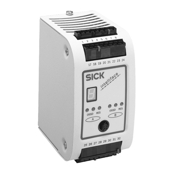
– for "Reset required" Display elements 3.3.1 LEDs and 7segment display The LEDs and 7-segment display indicate the operational status of the UE440/470. They are found on the front of the safety controller. Fig. 3: Status indicators o f the UE440/470 7segment displa y... - Page 16 Active signal at Enable input Bypass active Other For all other displays, refer to the meanings in Chapter 10.4 "Displays of displays the 7-segment display" on Page 90. © SICK AG • Industrial Safety Systems • Germany • All rights reserved 8010432/PG21/23-02-06...
-
Page 17: Configurable Functions
Functions such as the restart interlock, PSDI etc. can be configured in both the UE440/470 and in a device connected via EFI. The UE440/470 does not check whether or not these functions were configured with the connected devices. You must therefore check whether the configured safety application monitors the machine or system as planned. -
Page 18: Programs And Program Selector Switch
4.1.2 Programs and program selector switch You can configure up to five programs for your safety application(s) with the UE440/470. In each program, you can configure different links between the connected sensors and actuators and integrate the protective devices connected via EFI into the application(s). - Page 19 UE440. Program change for devices connected via EFI The status of the program selector switch of the UE440/470 can be transferred to a protective device connected via EFI. The program selector switch can be configured in such a way that the program change of the EFI device…...
-
Page 20: Program Change Via The Program Selector Switch
If the delay time at Out2 has already expired with the valid detection of a new program, a Notes program change occurs after the delay time has expired (for setting the shutdown delay of the Out2 output, see Section 4.2.12 on Page 37). © SICK AG • Industrial Safety Systems • Germany • All rights reserved 8010432/PG21/23-02-06... - Page 21 Sections 11.1.1 „Examples“ and 11.1.2 „Response times with program switching“ do not apply: Application B is linked to application A. Activating application B leads to the deactivation of application A. 8010432/PG21/23-02-06 © SICK AG • Industrial Safety Systems • Germany • All rights reserved...
-
Page 22: Automatic Reconfiguration
UE440/470 with a new UE440/470 with active automatic reconfiguration, the configuration of a C4000 connected via EFI may be overwritten by the new UE440/470 in certain circumstances. This is the case if the configuration saved in the UE440/470 contains the same type code as the connected C4000. - Page 23 The output of the release module signals a logical 1 (releases) when the necessary input criteria are met (AND link) at all the inputs used. 8010432/PG21/23-02-06 © SICK AG • Industrial Safety Systems • Germany • All rights reserved...
-
Page 24: Electro-Sensitive Protective Equipment
You can, for example... accept the information from the protective device via the protective fields. transfer the status of a program selector switch connected to the UE440/470 to the protective device. In this case, a different operating mode/program is switched to when switching occurs, both with the UE440/470 and the connected protective device. -
Page 25: Ossds Of The Ue440/470
If the EFI Status Information is processed by the UE440/UE470, please take into account ATTENTION that the OSSDs of the UE440/470 can be active even though the EFI device is in Lockout. Make sure that the BIT information „IO-Error-Status“ is processed as well. -
Page 26: Signal Output (Ado)
4.2.3 Signal output (ADO) You can configure up to eight configurable signal outputs (ADO) for the UE440/470. With the aid of the respective signal output, the safety controller can signal specific states. You can use this output for a relay or a PLC, for example. You can configure the signal outputs as inverted signal outputs too. -
Page 27: Two-Hand Control
A or B (for wiring options, see CDS). The electrical connection of the two-hand control is described in Chapter 6 "Electrical installation“ on Page 59. 8010432/PG21/23-02-06 © SICK AG • Industrial Safety Systems • Germany • All rights reserved... -
Page 28: Emergency Stop
Using organisational measures, ensure that the emergency stop input devices are actuated once after a certain interval. This is necessary, so that the UE440/470 can identify error conditions of an emergency stop input device which have arisen up until then. The interval is to be defined to suit the specific case dependant on the application. -
Page 29: External Device Monitoring (Edm)
4.2.7 External device monitoring (EDM) The EDM checks whether the contactors connected to an OSSD of the UE440/470 are in the correct state when the protective device responds. If you activate external device monitoring, the UE440/470 checks the contactors cyclically after each switch-off of the assigned OSSD and before the machine is restarted. -
Page 30: Reset Interlock
"Release of the application with a release module" on Page 38). With the machine control's external restart interlock: A reset button connected to the UE440/470 does not influence the machine restart. When all input conditions are fulfilled, the outputs of the UE440/470 are reactivated. - Page 31 Restart interlock tab. Reset If you want to activate the restart interlock on the UE440/470 (internal) and also a restart interlock on the machine (external), then each restart interlock gets a reset button. After actuating the reset button for the internal restart interlock (providing the initial conditions are in effect)…...
-
Page 32: Machine Cycle Start Condition (Start Input)
Reset and Start inputs at the release module influence the start behaviour of the machine. The input conditions for the release of the outputs of the UE440/470 or for the start of the machine can be, e.g:... - Page 33 The module is released with the LOW-HIGH edge at the input. A HIGH-LOW edge cancels the release. The release can then be achieved again via a LOW-HIGH edge at the input. 8010432/PG21/23-02-06 © SICK AG • Industrial Safety Systems • Germany • All rights reserved...
- Page 34 If the setting Start with rising edge and lock is configured for the machine cycle start behaviour, the module is released with a LOW-HIGH edge at the input. Additional signal changes at the Start input have no effect on the release. © SICK AG • Industrial Safety Systems • Germany • All rights reserved 8010432/PG21/23-02-06...
-
Page 35: Bypass
The bypass function is not in effect until the test signals for the key-operated switch for bypass have been identified by the UE440/470 (For the test pulse rate for the signal outputs O1.0 and O1.1, see Page 103). 200 ms after switching off the bypass, the system is again in a safe status (latency time). - Page 36 ATTENTION This is necessary so that the UE440/470 can identify an error condition of the key- operated switch for bypass or an error condition in its connection cable which occurs up until then. The interval is to be defined to suit the specific case dependant on the application.
-
Page 37: Shutdown Delay Of Output Out2
For the settable shutdown delay, refer to the Data sheet on Page 101. If you connect output Out2 to one of the OSSDs of the UE440/470, you can switch off a machine or system after a delay, for example. With this, you implement stop category 1 according to EN 418 for the assigned emergency stop input device (see Section 4.2.6... -
Page 38: Linking The Input Elements To Logic Modules
OSSDs are switched off. You can configure the following settings: Restart interlock (see Section 4.2.8 on Page 30) Machine cycle start behaviour (see Section 4.2.10 on Page 32) © SICK AG • Industrial Safety Systems • Germany • All rights reserved 8010432/PG21/23-02-06... -
Page 39: Application Name
Notes behaviour" setting and is defined in the release module. Take the following behaviour into account: If the connected sensors and the UE440/470 have different switch-on times after the supply voltage has been applied, an unintentional positive edge (LOW-HIGH transition) may arise at the input if the output of a sensor becomes active after the UE440/470. -
Page 40: Acknowledgement (Initialisation) Of Function Module
Context menu device symbol UE440/470, command Edit configuration draft… in Edit configuration draft window, context menu element symbol function module, command Element wizard…, Acknowledgement (initialisation) of function module tab. © SICK AG • Industrial Safety Systems • Germany • All rights reserved 8010432/PG21/23-02-06... -
Page 41: Machine Start
A cycle start must be carried out after the end of the machine cycle if the outputs of the UE440/470 have a safe status and no application start is required (see above). The machine cycle is ended when the machine cycle contact TDC is reached.The Out1 and Out2 outputs of the function module are deactivated there. -
Page 42: Acceptance/Bridging Of Logic
Using these function modules, you can also implement all functions described in Note Chapter 4.2 “Protective operation” from Page 22. The function modules have additional inputs for the machine cycle contacts (see Tab. 18 on Page 61). © SICK AG • Industrial Safety Systems • Germany • All rights reserved 8010432/PG21/23-02-06... -
Page 43: Principle Of Psdi Mode
1-PSDI (hydraulic presses), 2-PSDI (hydraulic presses), 1-PSDI (eccentric presses) or 2-PSDI (eccentric presses), command Element wizard..., PSDI mode tab. 8010432/PG21/23-02-06 © SICK AG • Industrial Safety Systems • Germany • All rights reserved... -
Page 44: Psdi Time Monitoring
Upward movement of the press. This cycle phase does not involve danger for all machines. Stoppage of the press. This cycle phase does not involve danger provided the 'Overrun monitoring' machine signal (SCC) has not been sent. © SICK AG • Industrial Safety Systems • Germany • All rights reserved 8010432/PG21/23-02-06... - Page 45 Constant testing for the SCC machine cycle contact is absolutely necessary (see Page 51). The electrical connection of the machine cycle contacts and the requirements for the contacts are described in Chapter 6 "Electrical installation" on Page 61. 8010432/PG21/23-02-06 © SICK AG • Industrial Safety Systems • Germany • All rights reserved...
-
Page 46: Start Sequence (Psdi Mode Initiation)
First interruption: PSDI start Interruption during the Last interruption: PSDI end. The UE470 switches back to green stopping phase as soon as the protective field interruption is ended. © SICK AG • Industrial Safety Systems • Germany • All rights reserved 8010432/PG21/23-02-06... -
Page 47: Releasing The Psdi Control
Check whether exiting of the ATTENTION protective field via the hazardous area can be prevented via corresponding measures, if necessary. 8010432/PG21/23-02-06 © SICK AG • Industrial Safety Systems • Germany • All rights reserved... -
Page 48: Eccentric Presses
The device-specific EFI status bits of the connected EFI devices can be evaluated or stimulated directly in the UE440/470. Thus, for example, monitoring cases in the S3000 can be changed over through the stimulation of the specific input bits of the S3000 via EFI. -
Page 49: Teach-In For C4000
UE440/470) or the C4000 (Teach-in key-operated switch is connected to the C4000). If the teach-in is initiated at the UE440/470, its OSSDs switch off during the teach-in. If the teach-in is initiated at the C4000, the OSSD of the C4000 switches off during the teach-in. -
Page 50: Teach-In Key-Operated Switch For C4000
Context menu device symbol UE440/470, command Edit configuration draft… in Edit configuration draft window, context menu element symbol of the sensor, command Element wizard…, Layout tab. © SICK AG • Industrial Safety Systems • Germany • All rights reserved 8010432/PG21/23-02-06... -
Page 51: Testing Of The Connected Input Devices And Sensors
If the configured input elements effect the OSSDs, (e.g. safety switches which switch off ATTENTION the OSSDs of the UE440/470) the response time of the OSSDs increase by the set input delay (see also Chapter 11.1 "Response times of OSSDs A and B" on Page 95). -
Page 52: Discrepancy Time
Element wizard…, Input filter tab. The discrepancy time does not affect the OSSD response time. Note © SICK AG • Industrial Safety Systems • Germany • All rights reserved 8010432/PG21/23-02-06... -
Page 53: Installation
Chapter 5 UE440/470 Installation The safety controller UE440/470 is designed for installation on a 35 mm mounting rail in accordance with EN 50 022. The positioning place must at least comply with enclosure rating IP 54. The following steps are necessary after mounting and installation:... -
Page 54: Electrical Installation
To ensure the necessary electromagnetic compatibility (EMC), functional earthing (FE) must be connected. The control cabinet or assembly casing of the UE440/470 must at least comply with enclosure rating IP 54. You must connect the UE440/470 to the same voltage supply as the connected protective devices. -
Page 55: Connections Of The Ue440/470
10 11 12 13 14 15 16 Use only encoded connections and label them! Dangerous faults could arise if the terminal strips are swapped and this goes undetected. ATTENTION 8010432/PG21/23-02-06 © SICK AG • Industrial Safety Systems • Germany • All rights reserved... - Page 56 Note the CDS. For this reason, use the pin assignment generated in the CDS for electrical installation. Context menu device symbol UE440/470, command Display configuration draft…. © SICK AG • Industrial Safety Systems • Germany • All rights reserved 8010432/PG21/23-02-06...
-
Page 57: Configuration Connection
Ensure protection from static-electricity discharge before connecting the configuration Notes cable (see Section 12.3.2 "CDS and connection cable" on Page 106). Always remove the plug from the configuration connection once you have completed configuration. 8010432/PG21/23-02-06 © SICK AG • Industrial Safety Systems • Germany • All rights reserved... -
Page 58: Connection Of Contact-Based Safety Sensors
The cables are to be installed in accordance with the category to be used, (EN 954-1); ATTENTION e.g. protected installation, single sheath with shielding etc. You can connect several single channel input devices and sensors to the UE440/470. Fig. 19: Examples for the connection of single channel... -
Page 59: Two-Hand Control
You can connect one emergency stop for each safety application. You must use N/C contacts for a single channel emergency stop. 8010432/PG21/23-02-06 © SICK AG • Industrial Safety Systems • Germany • All rights reserved... -
Page 60: Dual Channel Emergency Stop
You can connect separate reset buttons for each of the two safety applications which you can implement with the safety controller. Fig. 25: Example for connection of a reset button Use single channel N/O contacts for reset buttons. © SICK AG • Industrial Safety Systems • Germany • All rights reserved 8010432/PG21/23-02-06... -
Page 61: Machine-Cycle Contacts
The contact may be opened shortly after the machine is restarted. In accordance with Standard EN 963, we recommend implementing the machine cycle Recommendation contact BDC with two 1-channel NO contacts. 8010432/PG21/23-02-06 © SICK AG • Industrial Safety Systems • Germany • All rights reserved... -
Page 62: Teach-In Key-Operated Switch For C4000
The program mode selector switch is to be connected to 24 V ( ) without configured testing and to O1.0 ( ) with configured testing. © SICK AG • Industrial Safety Systems • Germany • All rights reserved 8010432/PG21/23-02-06... -
Page 63: External Device Monitoring (Edm)
OSSD. Spark-suppressed contactors extend the response time of the OSSDs depending on the Note type of the protective wiring. 8010432/PG21/23-02-06 © SICK AG • Industrial Safety Systems • Germany • All rights reserved... -
Page 64: Connection Of Active Sensors
Fig. 31: Example for connection of ESPE via EFI If the OSSD status is passed on to the UE440/470 via EFI, the response time of the Note OSSDs of the safety controller increases due to the transfer time. Take this into account when planning the safety distance/protective field size of the connected ESPE (see Chapter 11.1 "Response times of OSSDs A and B"... -
Page 65: Connection To The Outputs
PSDI signal lamp PSDI signal lamp 6.4.4 Signal output (ADO) You can make various signals of the UE440/470 available at the outputs, e.g. for a relay or an EPLC. Fig. 36: Example for connection of signal output (ADO) 8010432/PG21/23-02-06 ©... -
Page 66: Test Outputs
The outputs 01.0 and 01.1 are used as test outputs. The example shows the connection of a single channel and two dual channel sensors. Fig. 37: Example for the connection of several sensors with testing © SICK AG • Industrial Safety Systems • Germany • All rights reserved 8010432/PG21/23-02-06... -
Page 67: Application And Switching Examples
C4000 ( ). Both C4000s are connected via EFI. Two safety applications (application A and B) were configured in the UE440. The OSSD of the respective safety application is switched off due to the interruption of a protective field. The side access doors to the robot cells are monitored by safety switches ( ). - Page 68 14 % PFD at SIL 3 in application B with the specified application A with the specified marginal conditions after marginal conditions after 10 years. 10 years. © SICK AG • Industrial Safety Systems • Germany • All rights reserved 8010432/PG21/23-02-06...
-
Page 69: Access Protection With Point-Of-Operation Protection
An internal restart interlock is configured for the safety application. A signal lamp ( ) indicates that a reset is required after switch-off of the OSSD. The OSSD of the UE440 is reactivated by actuating the connected reset button ( ). - Page 70 Result The UE440 reaches a value of 14 % PFD at SIL 3 in application A with the specified marginal conditions after 10 years. © SICK AG • Industrial Safety Systems • Germany • All rights reserved...
-
Page 71: Hazardous Area Protection
Fig. 44: Simultaneous hazardous area protection The dangerous areas of two robot cells are protected via a UE440 with a safety laser scanner S3000 ( ). Two safety applications are configured in the UE440 for this. The S3000 monitors both hazardous areas with two simultaneous protective fields. The OSSD of the respective safety application is switched off due to an object in one of the protective fields. - Page 72 ) indicate that a reset is required after one of the OSSDs is switched off. The respective OSSD of the UE440 is reactivated by actuating the connected reset button ( Three emergency stop input devices are connected ( ) and switch off both safety applications (robot cells) simultaneously.
- Page 73 B with the specified application A with the specified marginal conditions after marginal conditions after 10 years. 10 years. Fig. 46: Connection of the simultaneous hazardous area protection 8010432/PG21/23-02-06 © SICK AG • Industrial Safety Systems • Germany • All rights reserved...
-
Page 74: Hazardous Point Protection
In a second application (implemented with the same UE470), access from behind the press is prevented with a cascading C2000 system ( ), and the horizontally mounted M2000 Guest serves as point-of-operation protection. © SICK AG • Industrial Safety Systems • Germany • All rights reserved 8010432/PG21/23-02-06... - Page 75 Two test outputs for testing of single or dual channel inputs (tests are offset by time for detection of cross-circuits) Dual channel outputs OSSD A OSSD B 8010432/PG21/23-02-06 © SICK AG • Industrial Safety Systems • Germany • All rights reserved...
- Page 76 PSDI mode In accordance with Standard EN 963, the machine cycle contact BDC must be Note implemented with two independent signals (e.g. two 1-channel NO contacts). © SICK AG • Industrial Safety Systems • Germany • All rights reserved 8010432/PG21/23-02-06...
-
Page 77: Hazardous Point Protection With Interior Area Protection
A restart interlock is configured for the safety applications. A signal lamp ( ) indicates that a reset is required after switch-off of the OSSD. The OSSD of the UE440 is reactivated by actuating the connected reset button ( ). - Page 78 The connection cables of the reset button are installed in separate sheathing lines or protected. Result The UE440 reaches a value of 17 % PFD at SIL 3 in application A with the specified marginal conditions after 10 years. Fig. 52: Connection of the...
-
Page 79: Hazardous Point Protection With Hazardous Area Protection
In the example, two separate protected applications are implemented with only one UE440. The hazardous point at the turntable of a robot cell is protected via a safety light curtain C4000 ( ). The hazardous area at the following robot cell is protected via a safety laser scanner S3000 ( ). - Page 80 17 % PFD at SIL 3 in application A with the application B with the specified marginal conditions specified marginal conditions after 10 years. after 10 years. © SICK AG • Industrial Safety Systems • Germany • All rights reserved 8010432/PG21/23-02-06...
- Page 81 Application and switching examples Operating Instructions Chapter 7 UE440/470 Fig. 55: Connection of the hazardous point protection with hazardous area protection 8010432/PG21/23-02-06 © SICK AG • Industrial Safety Systems • Germany • All rights reserved...
-
Page 82: Commissioning
Check all other actuators and sensors connected to the safety controller for proper functioning. Do not commission the UE440/470 until the behaviour of the sub-systems is safe and as predicted. © SICK AG • Industrial Safety Systems • Germany • All rights reserved... -
Page 83: System Self-Check After Switching On
Serial number correct? shows Waiting for Serial number correct? configuration Configuration date and time Configuration date and time Reconfiguration correct? correct? Ready for operation, 7segment display shows 8010432/PG21/23-02-06 © SICK AG • Industrial Safety Systems • Germany • All rights reserved... -
Page 84: Switch-On Sequence
Operating Instructions UE440/470 8.1.2 Switch-on sequence After switch-on, the UE440/470 runs through the switch-on cycle. During the switch-on cycle, the 7-segment display indicates the device status. When commissioning a UE440/470, the following display values are possible: Tab. 25: 7-segment display... -
Page 85: Full Approval Of The Application
Check the devices connected to the safety controller in accordance with the test notes from the accompanying operating instructions. For this purpose, the operating instructions of the ESPE from SICK AG contain the Note chapter "Tests before the first commissioning", and a "Manufacturer’s checklist" is found in the "Annex"... -
Page 86: Configuration
7-segment display. The initial configuration of the UE440/470 must first be performed offline to set the type of connections of the safety controller. Only then can you perform the electrical installation and transfer the configuration to the safety controller. -
Page 87: Default Delivery Status
Page 17). Please also read the user manual for the CDS and use the online help of the program. If desired, configure the connected ESPE from SICK AG in the CDS as well. Please read the corresponding operating instructions of the ESPE and the user manual for the CDS and use the online help of the program for this purpose. -
Page 88: Configuration Memory
If the configuration cannot be transferred to the ESPE (e.g. because the exchanged ESPE is not exactly the same), the 7-segment display shows Then reconfigure the ESPE and UE440/470 if necessary. © SICK AG • Industrial Safety Systems • Germany • All rights reserved 8010432/PG21/23-02-06... -
Page 89: Fault Diagnosis
"Test notes" on Page 85. ATTENTION The Lock-out operating status With certain malfunctions or a faulty configuration, the UE440/470 enters the safe Lock- out status. The 7-segment display of the safety controller shows the corresponding error. To place the device back in operation: Rectify the cause of the malfunction as per Tab. -
Page 90: Led Displays
10.4 Displays of the 7-segment display This section explains the meaning of the 7-segment display. A description of the positions and symbols used at the UE440/470 is found in Section 3.3 "Display elements" on Page 15. Tab. 28: Error displays of the... - Page 91 Two input signals at the Check the wiring for short-circuit. connections of the Check the program selector switch. program selector switch are identical 8010432/PG21/23-02-06 © SICK AG • Industrial Safety Systems • Germany • All rights reserved...
- Page 92 Check the wiring for short-circuit to 0 V. connection 2 after 0 V Short-circuit at OSSD A Check the wiring and rectify the error. between connections 1 and 2 © SICK AG • Industrial Safety Systems • Germany • All rights reserved 8010432/PG21/23-02-06...
- Page 93 Check whether a device with an EFI or impaired. connection is connected. A connection cannot be Check the connected device. established with a device connected via EFI. 8010432/PG21/23-02-06 © SICK AG • Industrial Safety Systems • Germany • All rights reserved...
-
Page 94: Extended Diagnostics
It allows you to diagnose the system status in case vague malfunctions occur. Detailed information is to be found… in the online help for the CDS. in the user manual for the CDS. © SICK AG • Industrial Safety Systems • Germany • All rights reserved 8010432/PG21/23-02-06... -
Page 95: Technical Data
Technical data 11.1 Response times of OSSDs A and B The response time of the UE440/470 is not to be set the same as the overall response time of the safety application. When considering the response time, you must calculate the response times for the individual signal paths (e.g. - Page 96 S3000: 21 ms ______ ms Internal processing time of the safety controller 10 ms Set shutdown delay ______ ms Response time of the OSSDs _______ ms © SICK AG • Industrial Safety Systems • Germany • All rights reserved 8010432/PG21/23-02-06...
- Page 97 This is why the following internal processing times of the safety controller must be assumed for calculation of the response time for this application. In "normal mode": 20 ms During program switching: 45 ms 8010432/PG21/23-02-06 © SICK AG • Industrial Safety Systems • Germany • All rights reserved...
-
Page 98: Examples
S3000: 21 ms 21 ms Internal processing time of the safety controller 10 ms Set shutdown delay 0 ms Response time of the OSSDs 151 ms © SICK AG • Industrial Safety Systems • Germany • All rights reserved 8010432/PG21/23-02-06... -
Page 99: Response Times With Program Switching
When calculating the response time with program switching, Note = delay time at the inputs = shutdown delay at the outputs (new program) = response time of the S3000 S3000 8010432/PG21/23-02-06 © SICK AG • Industrial Safety Systems • Germany • All rights reserved... - Page 100 131 ms Special case: Combination of UE440/470 with C4000 If the operating mode switch-over is transferred from the UE440/470 via EFI to a C4000, the input filter time of the C4000 is to be observed (see operating instructions "C4000 Standard/Advanced").
-
Page 101: Data Sheet
Depending on sensor connection. The external voltage supply must be capable of buffering brief mains failures of 20 ms as specified in EN 204-1. Within the limits of U 8010432/PG21/23-02-06 © SICK AG • Industrial Safety Systems • Germany • All rights reserved... - Page 102 In case of a fault (interruption of the 0V line), the leakage current flows to the OSSD line. The downstream control element must identify this condition as LOW. An EPLC (error-proof programmable logic controller) must identify this condition. © SICK AG • Industrial Safety Systems • Germany • All rights reserved 8010432/PG21/23-02-06...
- Page 103 ) When active, the outputs are tested cyclically (brief LOW). When selecting the downstream controllers, make sure that the test pulses do not result in deactivation when using the above parameters. 8010432/PG21/23-02-06 © SICK AG • Industrial Safety Systems • Germany • All rights reserved...
- Page 104 Limit the cable resistance of the individual wires to the downstream control element to this value so that a cross-circuit between the outputs is definitely identified. (In addition, note EN 60 204 Electrical Machine Equipment, Part 1: General Requirements.) © SICK AG • Industrial Safety Systems • Germany • All rights reserved 8010432/PG21/23-02-06...
-
Page 105: Dimensional Drawing
Technical data Operating Instructions Chapter 11 UE440/470 11.3 Dimensional drawing Fig. 58: Dimensional drawing 109.4 of UE440/470 (mm) 79.2 106.8 8010432/PG21/23-02-06 © SICK AG • Industrial Safety Systems • Germany • All rights reserved... -
Page 106: Ordering Information
System plug Operating instructions and CDS (Configuration & Diagnostic Software) on CD You will require the release code for the UE440/470 for CDS (see Section 12.3.2 "CDS Note and connection cable" on Page 106), which is not included with the delivery. -
Page 107: Annex
Annex Operating Instructions Chapter 13 UE440/470 Annex 13.1 Declaration of conformity 8010432/PG21/23-02-06 © SICK AG • Industrial Safety Systems • Germany • All rights reserved... -
Page 108: Checklist For The Manufacturer
6. Are you sure that the safety controller was tested fully for safety functionality after each configuration change? This checklist does not replace initial commissioning and regular tests by specialist personnel. © SICK AG • Industrial Safety Systems • Germany • All rights reserved 8010432/PG21/23-02-06... -
Page 109: List Of Tables
Tab. 33: Example for the calculation of the response time for operating mode 1.... 99 Tab. 34: Example for the calculation of the response time for operating mode 2.... 99 Tab. 35: Response time at program switching..............100 8010432/PG21/23-02-06 © SICK AG • Industrial Safety Systems • Germany • All rights reserved... -
Page 110: List Of Illustrations
Example for connection of ESPE via EFI ..............64 Fig. 32: Example for connection of ESPE via SDL .............. 64 Fig. 33: Example for connection of a "Reset required" signal lamp ........65 © SICK AG • Industrial Safety Systems • Germany • All rights reserved 8010432/PG21/23-02-06... - Page 111 Fig. 56: System self-check after switching on ..............83 Fig. 57: LEDs of the UE440/470 ..................90 Fig. 58: Dimensional drawing of UE440/470 (mm) ............105 8010432/PG21/23-02-06 © SICK AG • Industrial Safety Systems • Germany • All rights reserved...
- Page 112 Phone +81 (0)3 3358 1341 E-Mail info@sick.jp Nederlands Phone +31 (0)30 229 25 44 E-Mail info@sick.nl More representatives and agencies Norge in all major industrial nations at Phone +47 67 81 50 00 www.sick.com E-Mail austefjord@sick.no SICK AG | Waldkirch | Germany | www.sick.com...
Need help?
Do you have a question about the UE440 and is the answer not in the manual?
Questions and answers