
Related Manuals for SICK UE410-MU


Summarization of Contents
About this document
Function of this document
Explains the purpose and scope of the operating instructions for the safety controller.
Target group
Identifies the intended audience for the operating instructions, including engineers and operators.
Information depth
Details the types of information covered in the document regarding the safety controller.
Scope
Defines the applicability of the operating instructions to specific Flexi Classic modules.
Abbreviations
Lists and defines common abbreviations used throughout the document.
Symbols used
Explains the meaning of symbols for notes, actions, and warnings.
On safety
Qualified safety personnel
Defines the requirements for personnel qualified to mount, commission, and service the safety controller.
Applications of the device
Describes the Flexi Classic controller as a configurable system for safety applications.
Correct use
Specifies the intended use and conditions for the Flexi Classic modular safety controller.
General safety notes and protective measures
Provides essential safety guidelines and protective measures for safe operation and installation.
Environmental protection
Covers the device's design for minimal environmental impact and proper disposal.
Product description
Special features
Highlights the modular concept and interconnectivity of the Flexi Classic series.
Structure
Describes the overall system architecture with main modules and extensions.
UE410-MU main module
Provides detailed information on the UE410-MU main module, its applications, and programs.
Controls and status indicators
Explains the LED indicators and their meanings on the UE410-MU module.
Outputs
Describes the output wiring possibilities and safety-oriented signal requirements.
UE410-GU main module
Details the UE410-GU main module, its global emergency stop, and program selection.
Controls and status indicators
Explains the LED indicators and their meanings on the UE410-GU module.
Terminal assignment
Lists the terminal assignments for the UE410-GU module, including I/O and control signals.
Global emergency stop with the UE410-GU
Explains the principle and operation of the global emergency stop function with the UE410-GU.
Inputs
Describes the connection of emergency stop pushbuttons, local sensors, EDM, and reset buttons.
Outputs
Discusses output wiring, safety requirements, and connection of actuators.
Connection of a UE410-8DI
Explains how to connect a UE410-8DI to a UE410-GU for logic path control.
Power-up delay and response time of the UE410-GU
Details the calculation of power-up delay and response times for UE410-GU systems.
Diagnostics and troubleshooting for the UE410-GU
Guides on determining the cause of emergency stops using LED indicators.
UE410-XU module
Describes the UE410-XU as an input/output extension, its identical functionality to MU, and limitations.
Controls and status indicators
Refers to UE410-MU for controls, indicators, and terminal assignments for the UE410-XU.
UE410-MU/UE410-XU programs
Details the 9 settable programs for UE410-MU/XU, defining sensor types and logic.
UE410-GU programs
Details the 9 programs for the UE410-GU, including global/local stop and reset modes.
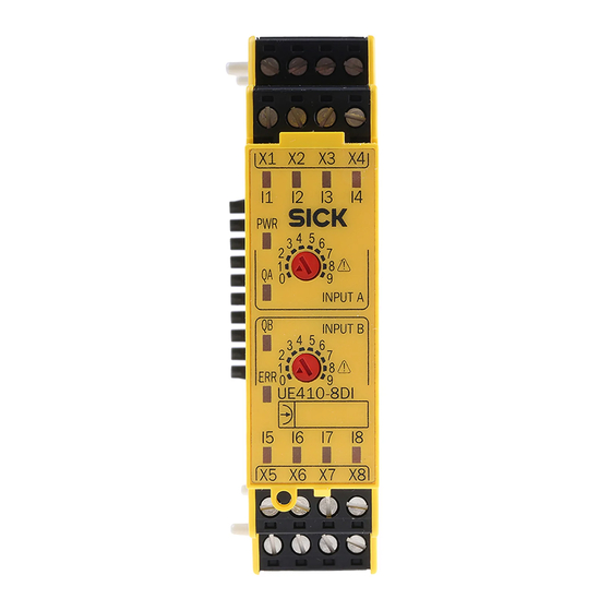
UE410-8DI input extension module
Describes the UE410-8DI module for input extension, its 8 inputs, and switch positions.
AND link
Explains the AND logic function for UE410-8DI switch settings 1-6.
OR link
Describes the OR logic function for UE410-8DI switch position 7.
Bypass
Explains the bypass function of UE410-8DI, overriding logic paths for 60 seconds.
Reciprocal assignment — Mirror mode
Details the mirror mode function where input B logic is assigned to input A, or vice versa.
Connection of sensors to the UE410-8DI
Provides guidance on connecting sensors to the UE410-8DI, considering test pulse generators.
Inputs and outputs
Lists the inputs and outputs for the UE410-8DI module, including test outputs.
UE410-2RO/UE410-4RO output modules
Introduces the UE410-2RO/4RO output modules for dual-channel contact-based outputs.
Output module UE410-2RO
Describes the UE410-2RO module's control input, internal relays, and shutdown paths.
Output module UE410-4RO
Details the UE410-4RO module with two control inputs, forming two shutdown paths.
Controls and status indicators
Explains the PWR and relay status indicators for UE410-2RO/4RO modules.
UE410-2RO inputs and outputs
Lists the assignments for B1, safety contacts, and EDM for the UE410-2RO.
UE410-4RO inputs and outputs
Lists assignments for B1, B2, safety contacts, and EDM for the UE410-4RO.
Special applications and functions
RE300 magnetic safety switch
Describes connecting and using RE300 magnetic safety switches with Flexi Classic modules.
IN4000 inductive safety switch
Details connecting IN4000 inductive safety switches to UE410-MU/XU units.
Testable single-beam photoelectric safety switches
Explains connecting testable single-beam photoelectric safety switches to various modules.
Two-hand operation/jog mode
Describes the setup and operation of two-hand controls and jog mode functions.
OR function
Explains how to implement the OR function using module switch positions or extension modules.
Muting function
Details the muting function for temporarily overriding safety devices with sensor signals.
Muting with two sensors
Explains muting with two sensors, including placement and activation conditions.
Muting cycle
Describes the sequence of events and conditions during a muting cycle.
Muting sensors
Lists sensor types used for muting and their role in evaluating muting conditions.
Placement of muting sensors
Provides important notes and guidelines for correctly positioning muting sensors.
Muting with two sensors (a sensor pair), crossed placement
Describes muting with two sensors in a crossed placement, including distance calculation.
4-sensor muting, sequential layout
Explains the setup for 4-sensor muting using a sequential layout with specific modules.
Muting with UE410-MU/UE410-XU
Details simple muting implementation using inputs I3/I4 on MU/XU modules.
SICK muting sensors
Lists available SICK optical muting sensors and their types.
Bypass
Explains the bypass function to override logic paths for a limited duration, including safety precautions.
Connecting S1, S2, S3
Details the connection of control inputs S1, S2, S3 for restart interlock, EDM, and retriggering.
Operation with restart interlock
Explains operation with a restart interlock, requiring a reset button and feedback circuit.
Operation without restart interlock
Describes operation where outputs activate based on sensor conditions without a reset button.
Operation with external device monitoring (EDM)
Details using EDM via S1, S2, S3 to monitor controlled contactors.
Retriggering of the delayed OSSDs
Explains how retriggering affects delayed OSSDs and off-delay behavior.
Grouping of subsystems
Discusses grouping modules into subsystems and preventing cross-circuits.
ENABLE input
Explains the ENABLE input's role in cascading circuits and its priority over other inputs.
Mounting/dismantling
Steps for mounting the modules
Provides step-by-step instructions for mounting the modules onto a 35 mm DIN mounting rail.
Steps for dismantling the modules
Details the procedure for safely removing modules, terminals, and end clips.
Removing the anti-manipulation cover
Explains how to remove and re-engage the optional anti-manipulation cover.
Application examples and connection diagrams
L21 on the UE410-MU/XU
Shows a connection diagram for L21 safety switches with UE410-MU/XU using program 3.2.
Emergency stop on the UE410-MU/XU
Illustrates an emergency stop connection to UE410-MU/XU using program 1.
RE300 on the UE410-MU/XU
Provides a connection example for RE300 safety switches with UE410-MU/XU using program 2.
Two-hand IIIC on the UE410-MU/XU
Shows a connection diagram for a two-hand switch (IIIC) with UE410-MU/XU using program 4.
C2000 and emergency stop on the UE410-MU/XU, two hazardous areas
Illustrates connecting C2000 and E-stop for two hazardous areas with UE410-MU/XU.
i11 on the UE410-MU/XU, two independent hazardous areas
Shows a connection diagram for i11 safety switches in two independent hazardous areas.
IN4000 on the UE410-MU/XU
Provides a connection example for IN4000 inductive safety switches with UE410-MU/XU.
C4000 on the UE410-MU/XU, 2-sensor muting
Shows a connection diagram for C4000 with 2-sensor muting using program 3.1.
Global emergency stop with two UE410-GU
Illustrates a global emergency stop connection using two UE410-GU modules in program 1.
Commissioning
Validation of the application
Outlines the crucial steps for validating the safety application before system commissioning.
Test notes
Provides essential notes and procedures for system testing and inspection.
Configuration
Accepting the system configuration
Describes the procedure for setting up and accepting the system configuration using the ENTER button.
Diagnostics
In the event of faults or errors
Guides on how to handle system faults and errors, including stopping operation and functional tests.
Replacement of a module
Explains the procedure and requirements for replacing modules, including configuration acceptance.
SICK support
Provides information on contacting SICK support for assistance with unresolved errors.
Error indications of the ERR error LED
Explains the meaning of ERR LED indications and the corresponding rectification steps.
Anti-manipulation measures
Details measures to prevent unauthorized manipulation of the system and the resulting error reactions.
Technical specifications
Data sheet
Provides comprehensive technical data sheets for various Flexi Classic modules.
UE410-MU/UE410-XU modules
Technical specifications for UE410-MU and UE410-XU modules, including electrical and input/output data.
UE410-GU module
Technical specifications for the UE410-GU module, covering supply, input, output, and timing data.
UE410-8DI input extension module
Technical specifications for the UE410-8DI input extension module, including power, input, output, and response times.
UE410-2RO/UE410-4RO output modules
Technical specifications for UE410-2RO and UE410-4RO output modules, detailing contacts and voltage/current ratings.
Dimensional drawings
Provides dimensional drawings for various Flexi Classic modules and gateways.
Ordering information
Available modules
Lists available modules, their parts, and corresponding part numbers for ordering.
Accessories/spare parts
Lists available accessories and spare parts, categorized by type.
Single-beam photoelectric safety switches
Lists part numbers for various single-beam photoelectric safety switches.
Non-contact safety switches
Lists part numbers for non-contact safety switches and related accessories.
Safety light curtains and multiple light beam safety devices
Lists safety light curtains and multiple light beam safety devices.
Safety laser scanners and safety camera system
Lists safety laser scanners and camera systems.
Muting lamps and cables
Lists part numbers for muting lamps and associated cables.
Anti-manipulation cover
Lists part numbers for anti-manipulation covers.
Annex
Compliance with EU directives
Provides information on the product's conformity with relevant EU directives.
Manufacturer’s checklist
Offers a checklist for manufacturers and installers to ensure proper installation and verification.
List of tables
Lists all tables included in the document for easy reference.
List of illustrations
Lists all figures and illustrations included in the document for easy reference.
Need help?
Do you have a question about the UE410-MU and is the answer not in the manual?
Questions and answers