Sign In
Upload
Manuals
Brands
SICK Manuals
Controller
UE 440
SICK UE 440 Manuals
Manuals and User Guides for SICK UE 440. We have
2
SICK UE 440 manuals available for free PDF download: Operating Instructions Manual
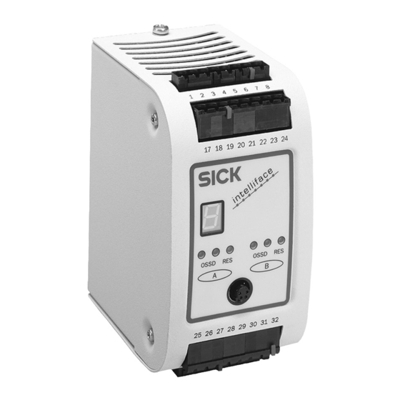
SICK UE 440 Operating Instructions Manual (112 pages)
Safety Controller
Brand:
SICK
| Category:
Controller
| Size: 3 MB
Table of Contents
Table of Contents
3
About this Document
6
Function of this Document
6
Target Group
6
Scope
6
Depth of Information
7
Abbreviations
7
Symbols Used
8
On Safety
9
Specialist Personnel
9
Applications of the Device
9
Correct Use
10
General Protective Notes and Protective Measures
10
Environmental Protection
11
Disposal
11
Material Separation
11
Product Description
12
Special Features
12
Operating Principle of the Device
13
Principle of the Device
13
Connectable Devices
14
Display Elements
15
Leds and 7Segment Display
15
Configurable Functions
17
Base Settings with the Configuration Wizard
17
Configuration Name
17
Programs and Program Selector Switch
18
Program Change Via the Program Selector Switch
20
Automatic Reconfiguration
22
Protective Operation
22
Electro-Sensitive Protective Equipment
24
Ossds of the UE440/470
25
Signal Output (ADO)
26
Devices and Sensors
26
Two-Hand Control
27
Emergency Stop
28
External Device Monitoring (EDM)
29
Reset Interlock
30
Machine Cycle Start Condition (Start Input)
32
Start Behaviour
32
Bypass
35
Shutdown Delay of Output Out2
37
Linking the Input Elements to Logic Modules
38
Release of the Application with a Release Module
38
Application Name
39
Function Module with Machine Cycle Contact Evaluation
39
Function Module Start Behaviour
39
Acknowledgement (Initialisation) of Function Module
40
Machine Start
41
Overrun Monitoring
41
Acceptance/Bridging of Logic
42
PSDI Mode with Safety Controller UE470
42
Principle of PSDI Mode
43
PSDI Time Monitoring
44
Significance of the Machine Cycle Contacts for PSDI Mode Operation
44
Start Sequence (PSDI Mode Initiation)
46
Releasing the PSDI Control
47
Overrun Monitoring
47
Deactivation of the Restart Interlock During Upward Movement
47
Eccentric Presses
48
PSDI Signal Lamp
48
Evaluation of Device-Specific EFI Status Bits
48
Teach-In for C4000
49
Teach-In Key-Operated Switch for C4000
50
Settings for Overlapping Functions
50
Complementary or Equivalent Input Evaluation
50
Testing of the Connected Input Devices and Sensors
51
Input Delay
51
Discrepancy Time
52
Installation
53
Electrical Installation
54
Connections of the UE440/470
55
System Connection
55
Configuration Connection
57
Connection of Contact-Based Safety Sensors
58
Single Channel Input Devices and Sensors
58
Dual Channel Input Devices and Sensors
58
Two-Hand Control
59
Single Channel Emergency Stop
59
Dual Channel Emergency Stop
60
Key-Operated Switch for Bypass
60
Reset Button
60
Machine-Cycle Contacts
61
Teach-In Key-Operated Switch for C4000
62
Program Selector Switch
62
External Device Monitoring (EDM)
63
Connection of Active Sensors
64
Electro-Sensitive Protective Equipment
64
Connection to the Outputs
65
Reset Required" Signal Lamp
65
Bypass Signal Lamp
65
PSDI Signal Lamp
65
Signal Output (ADO)
65
Test Outputs
66
Application and Switching Examples
67
Access Protection
67
Access Protection for Two Robot Cells
67
Access Protection with Point-Of-Operation Protection
69
Hazardous Area Protection
71
Simultaneous Hazardous Area Protection
71
Hazardous Point Protection
74
Hazardous Point Protection with PSDI Mode
74
Hazardous Point Protection with Interior Area Protection
77
Hazardous Point Protection with Hazardous Area Protection
79
Commissioning
82
Sequence for Commissioning
82
System Self-Check after Switching on
83
Switch-On Sequence
84
Full Approval of the Application
85
Test Notes
85
Tests before the First Commissioning
85
Regular Inspection of the Protective Device by Qualified Personnel
85
Daily Functional Checks of the Protective Device
85
Configuration
86
Default Delivery Status
87
Offline Configuration
87
Online Configuration
87
Configuration Memory
88
Fault Diagnosis
89
In the Event of Faults or Errors
89
SICK Support
89
LED Displays
90
Displays of the 7-Segment Display
90
Extended Diagnostics
94
Technical Data
95
Response Times of Ossds a and B
95
Examples
98
Response Times with Program Switching
99
Data Sheet
101
Dimensional Drawing
105
Ordering Information
106
Scope of Delivery
106
Available Systems
106
Accessories/Spare Parts
106
System Plug
106
CDS and Connection Cable
106
Connection Cable for Self-Made Cables
106
Annex
107
Declaration of Conformity
107
Checklist for the Manufacturer
108
List of Tables
109
List of Illustrations
110
Advertisement
SICK UE 440 Operating Instructions Manual (102 pages)
Safety Controller
Brand:
SICK
| Category:
Controller
| Size: 3 MB
Table of Contents
Table of Contents
3
1 About this Document
6
Function of this Document
6
Target Group
6
Scope
6
Depth of Information
7
Abbreviations
7
Symbols Used
8
2 On Safety
9
Specialist Personnel
9
Applications of the Device
9
Correct Use
10
General Protective Notes and Protective Measures
10
Environmental Protection
11
Disposal
11
Material Separation
11
3 Product Description
12
Special Features
12
Operating Principle of the Device
13
Principle of the Device
13
Connectable Devices
14
Display Elements
15
Leds and 7-Segment Display
15
4 Configurable Functions
17
Base Settings with the Configuration Wizard
17
Configuration Name
17
Operating Modes and Operating Mode Selector Switch
18
Automatic Reconfiguration
20
Protective Operation
20
Electro-Sensitive Protective Equipment
22
Ossds of the UE 440/470
23
Signal Output (ADO)
23
Devices and Sensors
24
Two-Hand Control
25
Emergency Stop
25
External Device Monitoring (EDM)
27
Reset Interlock
28
Bypass
30
Shutdown Delay of Output Out2
32
Linking the Input Elements to Logic Modules
32
Release of the Application with a Release Module
33
Application Name
33
PSDI Mode with Safety Controller UE 470
33
Principle of PSDI Mode
34
PSDI Time Monitoring
35
Significance of the Machine Cycle Contacts for PSDI Mode Operation
35
Start Sequence (PSDI Mode Initiation)
37
Releasing the PSDI Control
38
Overrun Monitoring
38
Deactivation of the Restart Interlock During Upward Movement
38
Eccentric Presses
39
PSDI Signal Lamp
39
Evaluation of Device-Specific EFI Status Bits
39
Teach-In for C 4000
40
Teach-In Key-Operated Switch for C 4000
41
Settings for Overlapping Functions
41
Complementary or Equivalent Input Evaluation
41
Testing of the Connected Input Devices and Sensors
42
Input Delay
42
Discrepancy Time
43
5 Installation
44
6 Electrical Installation
45
Connections of the UE 440/470
46
System Connection
46
Configuration Connection
48
Connection of Contact-Based Safety Sensors
49
Single Channel Input Devices and Sensors
49
Dual Channel Input Devices and Sensors
49
Two-Hand Control
50
Single Channel Emergency Stop
50
Dual Channel Emergency Stop
51
Key-Operated Switch for Bypass
51
Reset Button
51
Machine-Cycle Contacts
52
Teach-In Key-Operated Switch for C 4000
53
Operating Mode Selector Switch
53
External Device Monitoring (EDM)
54
Connection of Active Sensors
55
Electro-Sensitive Protective Equipment
55
Connection to the Outputs
56
Reset Required" Signal Lamp
56
Bypass Signal Lamp
56
PSDI Signal Lamp
56
Signal Output (ADO)
56
Test Outputs
57
7 Application and Switching Examples
58
Access Protection
58
Access Protection for Two Robot Cells
58
Access Protection with Point-Of-Operation Protection
60
Hazardous Area Protection
62
Simultaneous Hazardous Area Protection
62
Hazardous Point Protection
65
Hazardous Point Protection with PSDI Mode
65
Hazardous Point Protection with Interior Area Protection
68
Hazardous Point Protection with Hazardous Area Protection
70
8 Commissioning
73
Sequence for Commissioning
73
System Self-Check after Switching on
74
Switch-On Sequence
75
Full Approval of the Application
76
Test Notes
76
Tests before the First Commissioning
76
Regular Inspection of the Protective Device by Qualified Personnel
76
Daily Functional Checks of the Protective Device
76
9 Configuration
77
Default Delivery Status
78
Offline Configuration
78
Online Configuration
78
Configuration Memory
79
10 Fault Diagnosis
80
In the Event of Faults or Errors
80
SICK Support
80
LED Displays
81
Displays of the 7-Segment Display
81
Extended Diagnostics
85
11 Technical Data
86
Response Times of Ossds a and B
86
Examples
88
Data Sheet
90
Dimensional Drawing
94
12 Ordering Information
95
Scope of Delivery
95
Available Systems
95
Accessories/Spare Parts
95
System Plug
95
CDS and Connection Cable
95
Connection Cable for Self-Made Cables
95
13 Annex
96
Declaration of Conformity
96
Checklist for the Manufacturer
97
List of Tables
98
List of Illustrations
99
Advertisement
Related Products
SICK UE410-MU
SICK UE410-GU
SICK UE410-8DI
SICK UE410-XU
SICK UE410-2RO
SICK UE410-4RO
SICK UE 470
SICK UE4740
SICK UE49-2MM
SICK UE49-3MM
SICK Categories
Accessories
Security Sensors
Measuring Instruments
Scanner
Barcode Reader
More SICK Manuals
Login
Sign In
OR
Sign in with Facebook
Sign in with Google
Upload manual
Upload from disk
Upload from URL