
Related Manuals for SICK UE410-GU


Summary of Contents for SICK UE410-GU
- Page 1 O P E R A T I N G I N S T R U C T I O N S Flexi Classic Modular Safety Controller...
- Page 2 This document is protected by the law of copyright, whereby all rights established therein remain with the company SICK AG. Reproduction of this document or parts of this document is only permissible within the limits of the legal determination of Copyright Law. Alteration or abridgement of the document is not permitted without the explicit written approval of the company SICK AG.
-
Page 3: Table Of Contents
3.6.2 Program 2..................38 3.6.3 Programs 3.1 and 3.2 ..............39 3.6.4 Program 4..................40 3.6.5 Programs 5.1 and 5.2 ..............41 3.6.6 Program 6..................42 8011509/YPP0/2015-10-26 © SICK AG • Industrial Safety Systems • Germany • All rights reserved Subject to change without notice... - Page 4 Steps for mounting the modules..............80 Steps for dismantling the modules ..............81 Removing the anti-manipulation cover ............82 Electrical installation ....................83 © SICK AG • Industrial Safety Systems • Germany • All rights reserved 8011509/YPP0/2015-10-26 Subject to change without notice...
- Page 5 13.1 Compliance with EU directives..............118 13.2 Manufacturer’s checklist................118 13.3 List of tables....................119 13.4 List of illustrations ..................120 8011509/YPP0/2015-10-26 © SICK AG • Industrial Safety Systems • Germany • All rights reserved Subject to change without notice...
-
Page 6: About This Document
• commissioning and configuration • conformity and approval • care and maintenance Planning and using SICK protective devices also require specific technical skills which are not detailed in this documentation. When operating the Flexi Classic modular safety controller, the national, local and statu- tory rules and regulations must be observed. -
Page 7: Scope
A warning notice indicates an actual or potential risk or health hazard. They are designed to help you to prevent accidents. WARNING Read carefully and follow the warning notices! 8011509/YPP0/2015-10-26 © SICK AG • Industrial Safety Systems • Germany • All rights reserved Subject to change without notice... - Page 8 Muting lamp and Reset required lamp (not monitored) Lamp permanently ON: Muting active Lamp flashing 1 Hz: Reset required Pressure sensitive mats (4-wire system) Reset button Flexi Loop © SICK AG • Industrial Safety Systems • Germany • All rights reserved 8011509/YPP0/2015-10-26 Subject to change without notice...
- Page 9 Bypass function limited to 60 s Muting station with two inputs for muting sensors Retriggering Monitored semiconductor output Off delay ENABLE (EN) 8011509/YPP0/2015-10-26 © SICK AG • Industrial Safety Systems • Germany • All rights reserved Subject to change without notice...
- Page 10 Single-channel N/C contact/semiconductor input (e.g. sensors that can be tested) Switching mats, pressure-sensitive (4-wire system) Tab. 4: Logic symbols Symbol Logic OR link AND link © SICK AG • Industrial Safety Systems • Germany • All rights reserved 8011509/YPP0/2015-10-26 Subject to change without notice...
-
Page 11: On Safety
The Flexi Classic safety controller has been tested in accordance with UL 508. 8011509/YPP0/2015-10-26 © SICK AG • Industrial Safety Systems • Germany • All rights reserved Subject to change without notice... -
Page 12: Correct Use
EN 55 011. Group 1 encompasses all ISM devices in which intentionally generated and/or used conductor-bound RF energy that is required for the inner function of the device itself occurs. © SICK AG • Industrial Safety Systems • Germany • All rights reserved 8011509/YPP0/2015-10-26 Subject to change without notice... - Page 13 = Note the warnings and function descriptions of protective devices connected to the safety controller! Contact the respective manufacturer of the protective device if in doubt! 8011509/YPP0/2015-10-26 © SICK AG • Industrial Safety Systems • Germany • All rights reserved Subject to change without notice...
-
Page 14: Environmental Protection
Components Disposal by components Product Electronic recycling Housing, circuit boards, cables, connectors and electrical connecting pieces Packaging Paper/cardboard recycling Cardboard, paper © SICK AG • Industrial Safety Systems • Germany • All rights reserved 8011509/YPP0/2015-10-26 Subject to change without notice... -
Page 15: Product Description
Special features Fig. 1: Flexi Classic modular safety controller The Flexi Classic series is a safety controller concept comprising different modules that can be interconnected individually. This allows the system to be extended to up to 104 inputs or outputs. -
Page 16: Structure
S1, S2 and S3. The UE410-MU can control two applications acting independently as well as two applications that are dependent on each other. © SICK AG • Industrial Safety Systems • Germany • All rights reserved 8011509/YPP0/2015-10-26 Subject to change without notice... -
Page 17: Ue410-Gu Main Module
If relay outputs are required, these can be implemented with the UE410-2RO/UE410-4RO output modules. The UE410-GU does not support all data sets from all gateways. Note 8011509/YPP0/2015-10-26 © SICK AG • Industrial Safety Systems • Germany • All rights reserved Subject to change without notice... -
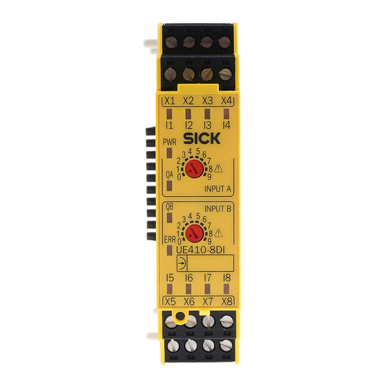
Page 18: Ue410-8Di Input Extension Module
All gateways have 4 non-safe application diagnostic outputs. The outputs are short-circuit protected (see also the Flexi Classic Gateways operating instructions). © SICK AG • Industrial Safety Systems • Germany • All rights reserved 8011509/YPP0/2015-10-26 Subject to change without notice... -
Page 19: Module Overview, Adjustments And Facilities For Connecting Sensors
3 different variants available (Not on UE410-xxxT0) Switch position 0-9 UE410-8DI Selection of the logic elements and of the safety sensors to be connected 8011509/YPP0/2015-10-26 © SICK AG • Industrial Safety Systems • Germany • All rights reserved Subject to change without notice... - Page 20 1, 2, 7, 8, 9 6, 7 6, 7 3, 7, 8 1, 2, 7, 8, 9 6, 7 6, 7 © SICK AG • Industrial Safety Systems • Germany • All rights reserved 8011509/YPP0/2015-10-26 Subject to change without notice...
- Page 21 2, 3, 6, 7, 8 1, 2, 6, 7, 8, – – – 1, 5, 6, 9 5, 6 2, 3, 8 2, 3, 8 8011509/YPP0/2015-10-26 © SICK AG • Industrial Safety Systems • Germany • All rights reserved Subject to change without notice...
-
Page 22: Ue410-Mu Main Module
9 programs that can be set with a screwdriver at the program switch are available. Fig. 3: Scheme programs 1-3 Fig. 4: Scheme program 4 © SICK AG • Industrial Safety Systems • Germany • All rights reserved 8011509/YPP0/2015-10-26 Subject to change without notice... - Page 23 Subsequent changes to the program or to the wiring (S1-S3) without saving will result in a safety-related shutdown. WARNING Q3 has various functions; see section 3.6 “UE410-MU/UE410-XU programs” on page 36. 8011509/YPP0/2015-10-26 © SICK AG • Industrial Safety Systems • Germany • All rights reserved Subject to change without notice...
-
Page 24: Controls And Status Indicators
S1-S3 flashes Expected signal is not present (e.g. EDM or Reset). Other indicators Device error, see chapter 10 “Diagnostics” on page 93 © SICK AG • Industrial Safety Systems • Germany • All rights reserved 8011509/YPP0/2015-10-26 Subject to change without notice... -
Page 25: Terminal Assignment
12.1 “Available modules” on page 112. When using multiple modules see section 4.12 “Grouping of subsystems” on page 78. 8011509/YPP0/2015-10-26 © SICK AG • Industrial Safety Systems • Germany • All rights reserved Subject to change without notice... -
Page 26: Outputs
© SICK AG • Industrial Safety Systems • Germany • All rights reserved 8011509/YPP0/2015-10-26 Subject to change without notice... -
Page 27: Ue410-Gu Main Module
For further information see section 3.7 “UE410-GU programs” on page 49. Subsequent changes to the program will result in a safety-related shutdown without saving. WARNING 8011509/YPP0/2015-10-26 © SICK AG • Industrial Safety Systems • Germany • All rights reserved Subject to change without notice... -
Page 28: Controls And Status Indicators
3.7 “UE410-GU programs” on page 49 ENTER Button for accepting the system configuration (Teach-in), see section 9.1 “Accepting the system configuration” on page 92 © SICK AG • Industrial Safety Systems • Germany • All rights reserved 8011509/YPP0/2015-10-26 Subject to change without notice... -
Page 29: Terminal Assignment
UE410-GU, then this status is indicated with a continuous high on output Q2. When using multiple modules see section 4.12 “Grouping of subsystems” on page 78. 8011509/YPP0/2015-10-26 © SICK AG • Industrial Safety Systems • Germany • All rights reserved Subject to change without notice... - Page 30 This wiring is saved with the configuration and checked each time on switching on. Fig. 9: Connecting several UE410-GU modules First module Module(s) in the middle Last module © SICK AG • Industrial Safety Systems • Germany • All rights reserved 8011509/YPP0/2015-10-26 Subject to change without notice...
-
Page 31: Local Emergency Stop On The Ue410-Gu
• The maximum actuation time for the reset button is ≤ 5 s. If one of these criteria is not met, the emergency stop is not reset. 8011509/YPP0/2015-10-26 © SICK AG • Industrial Safety Systems • Germany • All rights reserved Subject to change without notice... -
Page 32: Inputs
• All UE410-GU modules that are on a common global emergency stop cut-off path must be connected to the same GND connection. • Use appropriate components or devices in accordance with regulations and standards. © SICK AG • Industrial Safety Systems • Germany • All rights reserved 8011509/YPP0/2015-10-26 Subject to change without notice... -
Page 33: Connection Of A Ue410-8Di
Tab. 15. 8011509/YPP0/2015-10-26 © SICK AG • Industrial Safety Systems • Germany • All rights reserved Subject to change without notice... - Page 34 Also note the description of the LED indicators on the UE410-GU in section 3.4.1 “Controls and status indicators” on page 28 as well as chapter 10 “Diagnostics” on page 93. © SICK AG • Industrial Safety Systems • Germany • All rights reserved 8011509/YPP0/2015-10-26...
-
Page 35: Ue410-Xu Module
(not on UE410-xxxT0) Indicators, controls and terminal assignments are the same as on the UE410-MU main module (see Tab. 9-Tab. 11). 8011509/YPP0/2015-10-26 © SICK AG • Industrial Safety Systems • Germany • All rights reserved Subject to change without notice... -
Page 36: Ue410-Mu/Ue410-Xu Programs
• Input control circuit A acts on both safety outputs Q1/Q2 and Q3/Q4. • Input control circuit B acts only on the safety output Q3/Q4. © SICK AG • Industrial Safety Systems • Germany • All rights reserved 8011509/YPP0/2015-10-26 Subject to change without notice... -
Page 37: Program 1
Connecting of S3: with/without EDM Q3/Q4 with/without EDM Q3/Q4 ∂ retriggering ON ∂ retriggering OFF Outputs Undelayed OSSDs Q1/Q2 Delayable OSSDs Q3/Q4 8011509/YPP0/2015-10-26 © SICK AG • Industrial Safety Systems • Germany • All rights reserved Subject to change without notice... -
Page 38: Program 2
Connecting of S3: Retriggering with/without EDM Q3/Q4 with/without EDM Q3/Q4 ∂ retriggering ON ∂ retriggering OFF Undelayed OSSDs Q1/Q2 Outputs Delayable OSSDs Q3/Q4 © SICK AG • Industrial Safety Systems • Germany • All rights reserved 8011509/YPP0/2015-10-26 Subject to change without notice... -
Page 39: Programs 3.1 And 3.2
Delayable OSSD Q4 Output for muting lamp and Reset required lamp Q3 Q3 permanently High: Muting active Q3 1 Hz flashing: Reset required 8011509/YPP0/2015-10-26 © SICK AG • Industrial Safety Systems • Germany • All rights reserved Subject to change without notice... -
Page 40: Program 4
An off delay may not be set! Connecting of S3: with/without EDM Q3/Q4 Outputs Undelayed OSSDs Q1-Q4 No delayable OSSDs (two-hand standard) © SICK AG • Industrial Safety Systems • Germany • All rights reserved 8011509/YPP0/2015-10-26 Subject to change without notice... -
Page 41: Programs 5.1 And 5.2
An off delay may not be set! Connecting of S3: with/without EDM for Q3/Q4 Undelayed OSSDs Q1-Q4 Outputs No delayable OSSDs (two-hand standard) 8011509/YPP0/2015-10-26 © SICK AG • Industrial Safety Systems • Germany • All rights reserved Subject to change without notice... -
Page 42: Program 6
(not on UE410-xxxT0). Retriggering Connecting of S3: with/without EDM Q4 ∂ retriggering ON ∂ retriggering OFF Outputs Undelayed OSSDs Q1-Q3 Delayable OSSD Q4 © SICK AG • Industrial Safety Systems • Germany • All rights reserved 8011509/YPP0/2015-10-26 Subject to change without notice... -
Page 43: Program 7
(not on UE410-xxxT0). Connecting of S3: Retriggering with/without EDM Q4 ∂ retriggering ON ∂ retriggering OFF Undelayed OSSDs Q1-Q3 Outputs Delayable OSSD Q4 8011509/YPP0/2015-10-26 © SICK AG • Industrial Safety Systems • Germany • All rights reserved Subject to change without notice... -
Page 44: Program 8
(not on UE410-xxxT0). Retriggering Connecting of S3: with/without EDM Q4 ∂ retriggering ON ∂ retriggering OFF Undelayed OSSDs Q1-Q3 Outputs Delayable OSSD Q4 © SICK AG • Industrial Safety Systems • Germany • All rights reserved 8011509/YPP0/2015-10-26 Subject to change without notice... -
Page 45: Program 9
(not on UE410-xxxT0). Retriggering Connecting of S3: with/without EDM Q4 ∂ retriggering ON ∂ retriggering OFF Undelayed OSSDs Q1-Q3 Outputs Delayable OSSD Q4 8011509/YPP0/2015-10-26 © SICK AG • Industrial Safety Systems • Germany • All rights reserved Subject to change without notice... -
Page 46: Connection Of Sensors To The Ue410-Mu/Ue410-Xu
1500 ms X1-I1 Single-channel N/C contact Dual-channel complementary N/C X2-I2 contact cross-circuit detecting synchronisation time monitoring 1500 ms © SICK AG • Industrial Safety Systems • Germany • All rights reserved 8011509/YPP0/2015-10-26 Subject to change without notice... - Page 47 Dual-channel non-isolated Dual-channel non-isolated semiconductors semiconductors Dual-channel N/C contact, Dual-channel N/C contact, three-wire three-wire Single-channel N/C contact Single-channel N/C contact 8011509/YPP0/2015-10-26 © SICK AG • Industrial Safety Systems • Germany • All rights reserved Subject to change without notice...
- Page 48 N/C contact semiconductors X2-I2 cross-circuit detecting Dual-channel N/C contact, three-wire Single-channel N/C contact Tab. 18: Connection of sensors to the UE410-MU/UE410-XU © SICK AG • Industrial Safety Systems • Germany • All rights reserved 8011509/YPP0/2015-10-26 Subject to change without notice...
-
Page 49: Ue410-Gu Programs
Ux = independent 24 V supply that must be connected to the same GND connection as the power supply for the UE410-GU. Not connected, i.e. I3 must not be connected. 8011509/YPP0/2015-10-26 © SICK AG • Industrial Safety Systems • Germany • All rights reserved Subject to change without notice... - Page 50 OR limited 60 s with UE410-8DI — switch position 8 input B Switch position 8 input A is not permitted, UE410-GU switches to ERROR (configuration error). Output © SICK AG • Industrial Safety Systems • Germany • All rights reserved 8011509/YPP0/2015-10-26 Subject to change without notice...
-
Page 51: Ue410-8Di Input Extension Module
A bypass function that acts on the global cut-off path on the UE410-GU (switch position 8, input A on the UE410-8DI) is not permitted and will result in a configuration error (ERROR). 8011509/YPP0/2015-10-26 © SICK AG • Industrial Safety Systems • Germany • All rights reserved Subject to change without notice... -
Page 52: And Link
• Emergency stop button • Safety switch Single-channel N/C contact • ESPE (e.g. C4000) Dual-channel N/C contact, equivalent Dual-channel semiconductor output © SICK AG • Industrial Safety Systems • Germany • All rights reserved 8011509/YPP0/2015-10-26 Subject to change without notice... -
Page 53: Or Link
The bypass should only be activated through a conscious act of the operator WARNING and with a view of the hazardous area. 8011509/YPP0/2015-10-26 © SICK AG • Industrial Safety Systems • Germany • All rights reserved Subject to change without notice... -
Page 54: Reciprocal Assignment - Mirror Mode
2 × dual-channel, cross-circuit X2-I2 X4-I4 X6-I6 X8-I8 detection X1-I1 X3-I3 X5-I5 X7-I7 2 × dual-channel, cross-circuit X2-I2 X4-I4 X6-I6 X8-I8 detection © SICK AG • Industrial Safety Systems • Germany • All rights reserved 8011509/YPP0/2015-10-26 Subject to change without notice... - Page 55 With AND logic, unused inputs must be bridged to logical “1” (e.g. X4-I4, U -I4)! Tab. 24: Connection of sensors to the UE410-8DI 8011509/YPP0/2015-10-26 © SICK AG • Industrial Safety Systems • Germany • All rights reserved Subject to change without notice...
-
Page 56: Controls And Status Indicators
Function operating elements INPUT A 10-step rotary switches for setting an input circuit function (input group A or B) INPUT B © SICK AG • Industrial Safety Systems • Germany • All rights reserved 8011509/YPP0/2015-10-26 Subject to change without notice... -
Page 57: Inputs And Outputs
• one “safe enable current path” (Y14), dual-channel and not floating, • one “external device monitoring feedback circuit” (Y1/Y2), dual-channel and floating. Fig. 13: Internal structure UE410-2RO 8011509/YPP0/2015-10-26 © SICK AG • Industrial Safety Systems • Germany • All rights reserved Subject to change without notice... -
Page 58: Output Module Ue410-4Ro
• one “external device monitoring feedback circuit” (Y3/Y4), dual-channel and floating. The UE410-4RO therefore has twice the functionality of an UE410-2RO. Fig. 14: Internal structure UE410-4RO © SICK AG • Industrial Safety Systems • Germany • All rights reserved 8011509/YPP0/2015-10-26 Subject to change without notice... -
Page 59: Controls And Status Indicators
11 “Technical specifications” on page 96 N/O safety contact K3/K4, current-limited, see chapter 11 “Technical specifications” on page 96 8011509/YPP0/2015-10-26 © SICK AG • Industrial Safety Systems • Germany • All rights reserved Subject to change without notice... -
Page 60: Special Applications And Functions
• connecting of S1, S2, S3 – restart interlock – external device monitoring (EDM) • retriggering • grouping of subsystems • ENABLE input © SICK AG • Industrial Safety Systems • Germany • All rights reserved 8011509/YPP0/2015-10-26 Subject to change without notice... -
Page 61: Re300 Magnetic Safety Switch
(for example I1-X1), the even-numbered inputs/test outputs are not interconnected (for example I2-X2). 8011509/YPP0/2015-10-26 © SICK AG • Industrial Safety Systems • Germany • All rights reserved Subject to change without notice... -
Page 62: In4000 Inductive Safety Switch
Input I2 and test output X2 have to be jumpered. Terminal S2 may not be interconnected. A selection of the IN4000 safety sensors is available in section 12.2 “Accessories/spare parts” on page 115. © SICK AG • Industrial Safety Systems • Germany • All rights reserved 8011509/YPP0/2015-10-26 Subject to change without notice... -
Page 63: Testable Single-Beam Photoelectric Safety Switches
• UE410-8DI: The unused inputs have to be jumpered to the corresponding test outputs (for example the free inputs I2/X2 to I8/X8). 8011509/YPP0/2015-10-26 © SICK AG • Industrial Safety Systems • Germany • All rights reserved Subject to change without notice... - Page 64 All reflective surfaces and objects (for example material bins) must therefore be located at a minimum distance (a) rotational-symmetrically around the optical axis between the sender and receiver. © SICK AG • Industrial Safety Systems • Germany • All rights reserved 8011509/YPP0/2015-10-26 Subject to change without notice...
- Page 65 (mm) = 88.2 × 28 m × 10³ = 2469.6 mm The minimum distance (a) to the reflective surface has to amount to 2469.6 mm in this example. 8011509/YPP0/2015-10-26 © SICK AG • Industrial Safety Systems • Germany • All rights reserved Subject to change without notice...
-
Page 66: Two-Hand Operation/Jog Mode
In order to activate jog mode, terminal S2 remains unused. For two-hand applications, S2 is jumpered with the supply voltage +U It is not impossible to implement two-hand applications using a UE410-GU. Note © SICK AG • Industrial Safety Systems • Germany • All rights reserved 8011509/YPP0/2015-10-26 Subject to change without notice... -
Page 67: Or Function
An OR function that acts on the global cut-off path on the UE410-GU (switch position 7, input A on the UE410-8DI) is not permitted and will result in a configuration error (ERROR). 8011509/YPP0/2015-10-26 © SICK AG • Industrial Safety Systems • Germany • All rights reserved Subject to change without notice... -
Page 68: Muting Function
Always mount the muting lamp where it can be clearly seen! Note The muting lamp must be clearly visible from all sides of the hazardous area and for the system operator. © SICK AG • Industrial Safety Systems • Germany • All rights reserved 8011509/YPP0/2015-10-26 Subject to change without notice... -
Page 69: Muting With Two Sensors
• mechanical switches • controller signals SICK muting sensors An overview of the SICK muting sensors is available in the section 4.8 “SICK muting sensors” on page 73. 8011509/YPP0/2015-10-26 © SICK AG • Industrial Safety Systems • Germany • All rights reserved... -
Page 70: Placement Of Muting Sensors
Fig. 26: Principle of operation Detection zone Background of sensors with background suppression Sensor Material is Material is not detected detected © SICK AG • Industrial Safety Systems • Germany • All rights reserved 8011509/YPP0/2015-10-26 Subject to change without notice... -
Page 71: Muting With Two Sensors (A Sensor Pair), Crossed Placement
ESPE seen from the conveyor direction. • This placement is suitable for through-beam photoelectric switches and photoelectric reflex switches. 8011509/YPP0/2015-10-26 © SICK AG • Industrial Safety Systems • Germany • All rights reserved Subject to change without notice... -
Page 72: 4-Sensor Muting, Sequential Layout
“high” always overwrites a “low”. This type of muting may only be used after thorough risk analysis/error analysis. © SICK AG • Industrial Safety Systems • Germany • All rights reserved 8011509/YPP0/2015-10-26 Subject to change without notice... -
Page 73: Sick Muting Sensors
Through-beam photoelectric switch WS/WE27-3 WS260/WE260 Notes For the selection and settings for the SICK optical muting sensors in muting applications, the following applies: • The outputs must be PNP switching. • Other type series are possible. 8011509/YPP0/2015-10-26 © SICK AG • Industrial Safety Systems • Germany • All rights reserved... -
Page 74: Bypass
• It may not be possible to actuate the key-operated pushbutton for bypass in the hazard- ous area. • The safety controller ends the bypass automatically when an error occurs. © SICK AG • Industrial Safety Systems • Germany • All rights reserved 8011509/YPP0/2015-10-26 Subject to change without notice... -
Page 75: Connecting S1, S2, S3
Tab. 34: EDM by means Connecting of S2 Without EDM With EDM Manual reset (with restart interlock) Automatic reset (without restart interlock) 8011509/YPP0/2015-10-26 © SICK AG • Industrial Safety Systems • Germany • All rights reserved Subject to change without notice... -
Page 76: Retriggering Of The Delayed Ossds
Can be set up to x seconds Fig. 32: Retriggering OFF, without restart interlock Inputs Output Q Can be set up to x seconds 400 ms © SICK AG • Industrial Safety Systems • Germany • All rights reserved 8011509/YPP0/2015-10-26 Subject to change without notice... - Page 77 Q4, the N/C contacts of the respective contactors or output extensions have to be con- nected in series with the corresponding control inputs. 8011509/YPP0/2015-10-26 © SICK AG • Industrial Safety Systems • Germany • All rights reserved Subject to change without notice...
-
Page 78: Grouping Of Subsystems
= If several modules are used, the possibility of cross-circuits has to be excluded by means of appropriate cabling measures (protected installation, plastic-sheathed cable etc.). © SICK AG • Industrial Safety Systems • Germany • All rights reserved 8011509/YPP0/2015-10-26 Subject to change without notice... -
Page 79: Enable Input
OSSDs (Q1-Q4) go high. If a time delay has been set on Q3/Q4, the delay starts after the ENABLE input goes low. 8011509/YPP0/2015-10-26 © SICK AG • Industrial Safety Systems • Germany • All rights reserved Subject to change without notice... -
Page 80: Mounting/Dismantling
= Latch the module onto the DIN mounting rail by pressing it lightly in the direction of the arrow (2). © SICK AG • Industrial Safety Systems • Germany • All rights reserved 8011509/YPP0/2015-10-26 Subject to change without notice... -
Page 81: Steps For Dismantling The Modules
Fig. 37: Removing the plug-in terminals = Remove the plug-in terminals with wiring and the end clips. Fig. 38: Disconnecting the plug connection 8011509/YPP0/2015-10-26 © SICK AG • Industrial Safety Systems • Germany • All rights reserved Subject to change without notice... -
Page 82: Removing The Anti-Manipulation Cover
= The cover fastening is released by upward movements. The cover can be removed (1). = The cover is closed by engaging it. © SICK AG • Industrial Safety Systems • Germany • All rights reserved 8011509/YPP0/2015-10-26 Subject to change without notice... -
Page 83: Electrical Installation
RC circuits. Please also note that the selection of the arc suppression can increase the total response time of the safety function. 8011509/YPP0/2015-10-26 © SICK AG • Industrial Safety Systems • Germany • All rights reserved Subject to change without notice... - Page 84 = Mount the reset device so that it cannot be actuated by a person located in the ha- zardous area. When operating the reset device, the operator must have full visual command of the hazardous area. © SICK AG • Industrial Safety Systems • Germany • All rights reserved 8011509/YPP0/2015-10-26 Subject to change without notice...
-
Page 85: Application Examples And Connection Diagrams
Emergency stop on the UE410-MU/XU Program 1 with restart interlock and EDM Fig. 42: Connection of an emergency stop to the UE410-MU/XU 8011509/YPP0/2015-10-26 © SICK AG • Industrial Safety Systems • Germany • All rights reserved Subject to change without notice... -
Page 86: Re300 On The Ue410-Mu/Xu
Two-hand IIIC on the UE410-MU/XU Program 4 without restart interlock and with EDM Fig. 44: Connection of a two- hand switch IIIC to the UE410-MU/XU © SICK AG • Industrial Safety Systems • Germany • All rights reserved 8011509/YPP0/2015-10-26 Subject to change without notice... -
Page 87: C2000 And Emergency Stop On The Ue410-Mu/Xu, Two Hazardous Areas
UE410-MU/XU, two independent hazardous areas Program 8 with restart interlock and EDM Fig. 46: Connection of two i11 to the UE410-MU/XU, two hazardous areas 8011509/YPP0/2015-10-26 © SICK AG • Industrial Safety Systems • Germany • All rights reserved Subject to change without notice... -
Page 88: In4000 On The Ue410-Mu/Xu
Program 3.1 with restart interlock and EDM Fig. 48: Connection of a C4000 to the UE410-MU/XU, 2-sensor muting C4000 - FE must be connected © SICK AG • Industrial Safety Systems • Germany • All rights reserved 8011509/YPP0/2015-10-26 Subject to change without notice... -
Page 89: Global Emergency Stop With Two Ue410-Gu
Flexi Classic Global emergency stop with two UE410-GU Program 1 (global emergency stop only) Fig. 49: Global emergency stop with two UE410-GU 8011509/YPP0/2015-10-26 © SICK AG • Industrial Safety Systems • Germany • All rights reserved Subject to change without notice... -
Page 90: Commissioning
The software for the configuration documentation is available • on the Internet under http://www.sick.com/senscontrol • on the Flexi Classic Mini CD (part no. 2040332) © SICK AG • Industrial Safety Systems • Germany • All rights reserved 8011509/YPP0/2015-10-26 Subject to change without notice... -
Page 91: Test Notes
8011509/YPP0/2015-10-26 © SICK AG • Industrial Safety Systems • Germany • All rights reserved Subject to change without notice... -
Page 92: Configuration
Please refer to the description in section 10.4 “Error indications of the ERR error LED” on page 94. All later changes at the connection of S1, S2 and S3 will cause a lock-out (ERR). WARNING © SICK AG • Industrial Safety Systems • Germany • All rights reserved 8011509/YPP0/2015-10-26 Subject to change without notice... -
Page 93: Diagnostics
≤ C-XX to ≥ D-XX requires that connection I5 is exchanged with I6 and I7 is exchanged with I8. 8011509/YPP0/2015-10-26 © SICK AG • Industrial Safety Systems • Germany • All rights reserved Subject to change without notice... -
Page 94: Sick Support
S3 and ENABLE must always be wired on the UE410-MU/XU. Otherwise the outputs Q1-Q4 Note cannot be enabled. © SICK AG • Industrial Safety Systems • Germany • All rights reserved 8011509/YPP0/2015-10-26 Subject to change without notice... -
Page 95: Anti-Manipulation Measures
• Red ERR LED of the the voltage off and on again. master module (UE410-MU) flashes. • All other ERR LEDs to steady red 8011509/YPP0/2015-10-26 © SICK AG • Industrial Safety Systems • Germany • All rights reserved Subject to change without notice... -
Page 96: Technical Specifications
Maximum break time of the input signal without switching of the outputs (Q1-Q4) Time without sensor, the data for the sensors connected apply in addition. © SICK AG • Industrial Safety Systems • Germany • All rights reserved 8011509/YPP0/2015-10-26 Subject to change without notice... - Page 97 UE410-MU/XU (X1/X2) and UE410-8DI (X1-X8) must be I < 600 mA and the current on a Flexi Classic gateway must be I < 100 mA. If this total current is insufficient, please contact the SICK hotline. 8011509/YPP0/2015-10-26 ©...
- Page 98 Response time not including Flexi Loop and not including sensor. Also take into account the response times of Flexi Loop and the sensors connected. © SICK AG • Industrial Safety Systems • Germany • All rights reserved 8011509/YPP0/2015-10-26 Subject to change without notice...
- Page 99 5-7 lb – Tightening torque UE410-xx4…, UE410-xxx4… – Connection cross-section AWG 30-12 (only use 60/75 °C copper flexible wire) Cascading subsystems. 8011509/YPP0/2015-10-26 © SICK AG • Industrial Safety Systems • Germany • All rights reserved Subject to change without notice...
- Page 100 6.0 % 2.5 % 6.0 % 2.5 % For detailed information on the safety design of your machine/system, please contact your local SICK representative. © SICK AG • Industrial Safety Systems • Germany • All rights reserved 8011509/YPP0/2015-10-26 Subject to change without notice...
-
Page 101: Ue410-Gu Module
Duration of actuation of the reset 50 ms – button (I6) Time without sensor, in addition the data for the sensors connected apply. 8011509/YPP0/2015-10-26 © SICK AG • Industrial Safety Systems • Germany • All rights reserved Subject to change without notice... - Page 102 UE410-GU/XU (X1/X2) and UE410-8DI (X1-X8) must be I < 600 mA and the current on a Flexi Classic gateway must be I < 100 mA. If this total current is insufficient, please contact the SICK hotline. © SICK AG • Industrial Safety Systems • Germany • All rights reserved...
- Page 103 Response time not including Flexi Loop and not including sensor. Also take into account the response times of Flexi Loop and the sensors connected. The input voltage levels (I1-I6, I ) must be met. 8011509/YPP0/2015-10-26 © SICK AG • Industrial Safety Systems • Germany • All rights reserved Subject to change without notice...
- Page 104 6.0 × 10 % of SIL3 6.0 % 6.0 % For detailed information on the safety design of your machine/system, please contact your local SICK subsidiary. © SICK AG • Industrial Safety Systems • Germany • All rights reserved 8011509/YPP0/2015-10-26...
-
Page 105: Ue410-8Di Input Extension Module
UE410-MU/XU (X1/X2) and UE410-8DI (X1-X8) must be I < 600 mA and the current on a Flexi Classic gateway must be I<100 mA. If this total current is insufficient, please contact the SICK hotline. Time without sensor, the data for the sensors connected apply in addition. - Page 106 Response time not including Flexi Loop and not including sensor. Also take into account the response times of Flexi Loop and the sensors connected. © SICK AG • Industrial Safety Systems • Germany • All rights reserved 8011509/YPP0/2015-10-26 Subject to change without notice...
-
Page 107: Ue410-2Ro/Ue410-4Ro Output Modules
– – UE410-4RO – – For detailed information on the safety design of your machine/system, please contact your local SICK representative. 8011509/YPP0/2015-10-26 © SICK AG • Industrial Safety Systems • Germany • All rights reserved Subject to change without notice... - Page 108 6 A (gG), per current path Usage category AC-15: U 250 V, I DC-13: U 24 V, I Time from LOW on B1/B2 to relay drop-out. © SICK AG • Industrial Safety Systems • Germany • All rights reserved 8011509/YPP0/2015-10-26 Subject to change without notice...
- Page 109 The total output current is limited. Maximum total current for all relay modules on Y14 and Y24 is I < 400 mA. 8011509/YPP0/2015-10-26 © SICK AG • Industrial Safety Systems • Germany • All rights reserved Subject to change without notice...
- Page 110 Depending on PFHd value, ambient temperature, load and switching operations (see Tab. 46) For detailed information on the safety design of your machine/system, please contact your local SICK representative. © SICK AG • Industrial Safety Systems • Germany • All rights reserved...
-
Page 111: Dimensional Drawings
UE410-XU, UE410-8DI, UE410-2RO, UE410-4RO, UE410-PRO, UE410-DEV, UE410-CAN modules Fig. 51: Dimensional drawing 114.4 UE410-XU, UE410-8DI, UE410-2RO, UE410-4RO, UE410-PRO, UE410-DEV, UE410-CAN (mm) 22.5 93.7 120.8 8011509/YPP0/2015-10-26 © SICK AG • Industrial Safety Systems • Germany • All rights reserved Subject to change without notice... -
Page 112: Ordering Information
4 inputs/4 outputs No delay Plug-in screw terminals UE410-XU3T5 Input/output extension module 6032470 4 inputs/4 outputs Delay possible: 0-5 s Plug-in screw terminals © SICK AG • Industrial Safety Systems • Germany • All rights reserved 8011509/YPP0/2015-10-26 Subject to change without notice... - Page 113 Delay possible: 0-50 s Plug-in spring terminals UE410-XU4T300 Input/output extension module 6032674 4 inputs/4 outputs Delay possible: 0-300 s Plug-in spring terminals 8011509/YPP0/2015-10-26 © SICK AG • Industrial Safety Systems • Germany • All rights reserved Subject to change without notice...
- Page 114 Plug-in screw terminals UE410-EN3 Modbus TCP/IP and Ethernet TCP/IP gateway 1042193 Plug-in screw terminals UE410-EN4 PROFINET IO gateway 1044078 Plug-in screw terminals © SICK AG • Industrial Safety Systems • Germany • All rights reserved 8011509/YPP0/2015-10-26 Subject to change without notice...
-
Page 115: Accessories/Spare Parts
Single-beam photoelectric safety switch, receiver, 6034862 24 V DC, operating range 60 m, PNP, physical size M30, M12 × 4 plug 8011509/YPP0/2015-10-26 © SICK AG • Industrial Safety Systems • Germany • All rights reserved Subject to change without notice... -
Page 116: Non-Contact Safety Switches
T4000 Direct connecting cable 6022152 G10MA M12, 8-pin with 10 m cable DOL-0804-G10M 6010754 RE13/RE31 connecting cable M8, 4-pin with 10 m cable © SICK AG • Industrial Safety Systems • Germany • All rights reserved 8011509/YPP0/2015-10-26 Subject to change without notice... -
Page 117: Safety Light Curtains And Multiple Light Beam Safety Devices
2019910 12.2.6 Anti-manipulation cover Tab. 53: Part number anti- Part Description Part number manipulation cover AM cover 10 anti-manipulation covers 5319789 8011509/YPP0/2015-10-26 © SICK AG • Industrial Safety Systems • Germany • All rights reserved Subject to change without notice... -
Page 118: Annex
6. Are you sure that the safety controller was tested fully for safety functionality after each configuration change? This checklist does not replace the initial commissioning and regular tests by qualified safety personnel. © SICK AG • Industrial Safety Systems • Germany • All rights reserved 8011509/YPP0/2015-10-26 Subject to change without notice... -
Page 119: List Of Tables
Tab. 39: Data sheet UE410-MU/UE410-XU..............96 Tab. 40: PFD and PFHd values for UE410-MU/ UE410-XU..........100 Tab. 41: Data sheet UE410-GU..................101 8011509/YPP0/2015-10-26 © SICK AG • Industrial Safety Systems • Germany • All rights reserved Subject to change without notice... -
Page 120: List Of Illustrations
Fig. 26: Principle of operation of sensors with background suppression......70 Fig. 27: Muting with two sensors, crossed placement ............ 71 © SICK AG • Industrial Safety Systems • Germany • All rights reserved 8011509/YPP0/2015-10-26 Subject to change without notice... - Page 121 Dimensional drawing UE410-MU and E410-GU (mm) ........111 Fig. 51: Dimensional drawing UE410-XU, UE410-8DI, UE410-2RO, UE410-4RO, UE410-PRO, UE410-DEV, UE410-CAN (mm)............ 111 8011509/YPP0/2015-10-26 © SICK AG • Industrial Safety Systems • Germany • All rights reserved Subject to change without notice...
- Page 122 Annex Chapter 13 Operating instructions Flexi Classic © SICK AG • Industrial Safety Systems • Germany • All rights reserved 8011509/YPP0/2015-10-26 Subject to change without notice...
- Page 123 Annex Operating instructions Chapter 13 Flexi Classic 8011509/YPP0/2015-10-26 © SICK AG • Industrial Safety Systems • Germany • All rights reserved Subject to change without notice...
- Page 124 Phone +386 (0)1-47 69 990 E-Mail ghk@sick.com.hk E-Mail office@sick.si Hungary South Africa Phone +36 1 371 2680 Phone +27 11 472 3733 More representatives and agencies E-Mail office@sick.hu E-Mail info@sickautomation.co.za at www.sick.com SICK AG | Waldkirch | Germany | www.sick.com...
Need help?
Do you have a question about the UE410-GU and is the answer not in the manual?
Questions and answers