Table of Contents
Advertisement
Quick Links
Advertisement
Table of Contents

Related Manuals for ESAB DTE 255


Summary of Contents for ESAB DTE 255
-
Page 2: Table Of Contents
..........AP09 DTE 255 AC snubber ’A’ circuit board . - Page 3 INSTRUCTIONS ..............SAFETY .
-
Page 4: Read This First
: DTE 200 with serial no. 810--xxx--xxxx, 844--xxx--xxxx, 934--xxx--xxxx, 948--xxx--xxxx, 246--xxx--xxxx. The DTE 200 and DTE 255 are designed and tested in accordance with international and European standard IEC/EN 60974- -1 and EN 50199. On completion of service or repair work, it is the responsibility of the person(s) etc. -
Page 5: Introduction
INTRODUCTION On the DC side, this generation of ESAB inverters for AC/DC welding is based on fast- - switching IGBTs (Insulated Gate Bipolar Transistors). IGBT module Q05 is a half- - wave bridge with integral freewheel diodes. Low saturation voltage IGBTs are fitted in the AC converter. Q01 - - Q04 are single switch modules with integral freewheel diodes. -
Page 6: Technical Data
TECHNICAL DATA DTE 200 DTE 255 Permissible load at 25% duty cycle, MMA 250 A / 30 V 35% duty cycle, MMA 170 A / 27 V 60% duty cycle, MMA 130 A / 25 V 200 A / 28 V... -
Page 7: Load Characteristics
LOAD CHARACTERISTICS DTE 200 DTE 255 - - 7 - - cdte1de1... -
Page 8: Component Description
Use proper static- -proof bags and boxes. This component description refers to the diagram for the DTE 255 on page 12 and for the DTE 200 on page 14. Data for components not mentioned here may be found in the spare parts list. - Page 9 Cooling fan, DC unit (230V AC). EV02, EV03 DTE 255: Cooling fans, AC unit (230V AC). To check if the fans are electrically sound: disconnect the supply to the fans and measure their resistance with an ohmmeter across terminal XT23. The resistance must be 315Ω...
- Page 10 Wire 007 must be connected to the positive (+) pole of V02. Diode, used with C09 and R3 to limit the voltage between plus and minus on the IGBTs (Q01 - - Q04). Only for DTE 255. Diode module. When measured with a diode tester the forward voltage drop is about 0.2 - - 0.3V.
- Page 11 - - 11 - - cdte1de1...
-
Page 12: Dte 255 Wiring Diagram
DTE 255 WIRING DIAGRAM - - 12 - - cdte1de1... - Page 13 - - 13 - - cdte1de1...
-
Page 14: Dte 200 Wiring Diagram
DTE 200 WIRING DIAGRAM - - 14 - - cdte1de1... - Page 15 - - 15 - - cdte1de1...
-
Page 16: Description Of Operation
DESCRIPTION OF OPERATION AP01 DC Control circuit board Circuit board AP01 controls the DC part of the machine. It also acts as an interface between processor board AP04 and circuit boards AP02, AP05 and AP06. Some of the functions of those circuit boards are also described here. -
Page 17: Ap01:2 Temperature And Fan Monitoring
Overwiev of the power supplies from circuit board AP01 AP01:2 Temperature and fan monitoring Overwiev of the temperature monitoring on circuit board AP01 Temperature sensor ST01 is fitted at one of the screws securing the IGBT module Q05. Sensor ST03 is fitted on the main transformer TM01. The sensors are PTC resistors which are monitored by circuit board AP01. -
Page 18: Ap01:3A Lift Arc Test Voltage
AP01:3a Lift Arc Test voltage Lift Arc test voltage In Lift Arc mode a test voltage is used to detect when the electrode is in contact with the workpiece. Normally the signal test from AP04 is +15V. When the torch trigger is depressed it changes to 0V, activating transistors Q228 and Q226. -
Page 19: Ap01:4 Hf Generator
An output from AP04 activates the start voltage, which is connected in parallel with the welding voltage by transistor Q14. The start voltage is activated as long as the HF genarator is active: see AP01:4. AP01:4 HF Generator Control circuits for the HF start unit The HF generator, AP13, is controlled from processor board AP04. -
Page 20: Ap01:6 Gate Pulses From Ap01
AP01:6 Gate pulses from AP01 IGBT drivers, symmetry monitoring and symmetry control The IGBT drivers, symmetry monitoring and symmetry control employ opto couplers with an isolation voltage of 5kV. When there is no signal from the symmetry circuits on AP02, IC81:3 and IC83:3 are connected to 0 V. - Page 21 Before attempting to measure the gate pulses to the IGBTs, it is essential to disconnect the power supply from rectifier unit AP03. DTE 255: Switch off the machine and remove wires 090 and 007 from rectifier unit AP03. See the wiring diagram on page 12.
-
Page 22: Ap01:7 Primary Overcurrent Protection
AP01:7 Primary overcurrent protection Primary current monitoring circuits Current transformer TR1 is mounted on circuit board AP02, see the diagram on page 27. The signal from TR1 is rectified on AP01. Potentiometer R401 (which is factory- -adjusted) adjusts the level of the signal to that needed to shut down the PWM controller. -
Page 23: Ap01:8 Arc Voltage Sensing
AP01:8 Arc voltage sensing Signal path for arc voltage sensing in the DTE 255 IC32 has a gain of 0.1, which means that a welding voltage of 10V produces 1V at the output ( ). The signal is connected to AP05 and AP04, and used UNORM for process control on AP04. -
Page 24: Ap01:9 Current Monitoring
The minimum current can be adjusted with R301, and must be 5- - 7A. The maximum current can be adjusted with R335, and must be 250 ±5A for the DTE 255 and 200 ±5A for the DTE 200. R333 is used to adjust the feedback of the controller (e.g. adjust R333 when the arc is too noisy). -
Page 25: Ap01 Component Positions
AP01 Component positions Component positions for version 1 of circuit board AP01, with part no. 0486 657 880 WARNING: high voltage in the shaded areas - - 25 - - cdte1de1... - Page 26 Component positions for version 2 of circuit board AP01, with part no. 0486 810 880 WARNING: high voltage in the shaded areas - - 26 - - cdte1de1...
-
Page 27: Ap02 Primary Igbt Circuit Board
Comments to the diagram above: Capacitor C05 is fitted only in the DTE 255. In the DTE 200, main transformer TM01 has only one primary winding. Capacitors C1, C2, C13 and C14 are fitted to circuit board AP02 only in the DTE 255. Test instructions for the IGBT module are on page 61. -
Page 28: Ap02 Component Positions
AP02 Component positions Component positions, circuit board AP02 When connectors XC and XD have been disconnected, make sure that both sleeves of the two connectors are properly reconnected. See the diagram on previous page. The machine will also work with one of the primary windings connected, but the main transformer, TM01, will be overheated. -
Page 29: Ap03 Mains Rectifier Circuit Board
AP03 Mains rectifier circuit board This circuit board is used only in the DTE 255. Circuit diagram for circuit board AP03 Component positions for circuit board AP03 - - 29 - - cdte1de1... -
Page 30: Ap04 Processor Circuit Board
AP04 Processor circuit board There are two versions of the board, the in- - and output signals are the same, both versions fits in any machine having version 1 or 2 of the front panel circuit board, AP05. Machines having version 3 of circuit board AP05 must have version 2 of AP04. -
Page 31: Ap04 Component Positions
AP04 Component positions Component positions for version 1 of circuit board AP04, part no. 0486 665 880 - - 31 - - cdte1de1... - Page 32 Component positions for version 2 of circuit board AP04, part no. 0486 770 880 - - 32 - - cdte1de1...
-
Page 33: Ap05 Front Panel Circuit Board
AP05 Front panel circuit board There are three versions of circuit board AP05. Version 1 is used in the DTE 255 up to serial no. 844- - 950- -xxxx. Version 2 is used in all other machines up to and including serial no. -
Page 34: Ap05:3 Analogue Settings
Adjustment for the maximum reading of the display (250A for the DTE 255 and 200A for the DTE 200). Is used in the DTE 200 to provide correct reading of the 200A range. XA6 and 8 are bridged in the DTE 255. - - 34 - - cdte1de1... - Page 35 Trim potentiometers on version 1 and 2 of circuit board AP05 Analogue settings, version 2 of circuit board AP05. - - 35 - - cdte1de1...
-
Page 36: Ap05:4A Digital Display
AP05:4a Digital display Valid for version 1 and 2 of circuit board AP05 Drive circuit for the digital display, version 1 and 2 of AP05 When a remote control is used version 1 displays always the welding current which is set by potentiometer R1 on the front panel. Version 2 displays the value set by the remote control. -
Page 37: Ap05:4B Analogue Settings And Digital Display
AP05:4b Analogue settings and digital display Valid for version 3 of circuit board AP05 Analogue settings and digital display, version 3 of circuit board AP05 All analogue signals from AP05 to the processor board AP04 are related to a regulated 5V supply from AP04 ( ). -
Page 38: Ap05:5 Error Monitoring
Adjustment for the maximum current reference (250A for the DTE 255 and 200A for the DTE 200). Is used in the DTE 200 to provide correct reading of the 200A range. XA6 and 8 are bridged in the DTE 255. AP05:5 Error monitoring... -
Page 39: Ap05 Version 1, Component Positions
AP05 Version 1, Component positions Version 1 of circuit board AP05 is used in the DTE 255 before serial no. 844- - 950- -xxxx. This version has not been used in the DTE 200. NOTE: when this version of AP05 is replaced by... -
Page 40: Ap05 Version 2, Component Positions
AP05 Version 2, Component positions Version 2 of circuit board AP05 is used in all DTE 200 and in DTE 255 from serial no. 844- -950- - xxxx up to and including ser. no. 948- -xxx- - xxxx. The following improvements have been made to... -
Page 41: Ap05 Version 3, Component Positions
AP05 Version 3, Component positions Version 3 of circuit board AP05 is used from serial no. 246- - xxx- -xxxx The following changes have been made to version 3 of the circuit board: S SMD components are used for most of the functions. -
Page 42: Ap06 Start And Remote Control Circuit Board
The internal current setting limits the current set by the remote control. See page 71 for instructions. DTE 255 before serial number 844- -950- -xxxx, with version 1 of circuit board AP05: When using a remote control, the display will show the possible maximum current and not the current set by the remote control. - Page 43 DTE 255 from serial number 844- - 950- -xxxx and all DTE 200: When using a remote control, the display will show the current set by the remote control. Component positions for circuit board AP06 It is important that the connection shown above is properly connected to the front plate of the machine and to the chassis connection cable marked 509.
-
Page 44: Ap07 Ac Control Circuit Board
AP07 AC control circuit board All functions on this circuit board are galvanically isolated from the rest of the machine, except GND3, which is connected to negative. See the the diagram on page 45. From serial no. 246- -xxx- -xxxx a new version of the board is fitted to the machines. This description applies to all versions of the board. -
Page 45: Ap07:2 Gate Pulses From Ap07
Is used during polarity change. The time for polarity change is controlled by IC1, which holds its outputs T1 - - T4 at 0.5V for about 200ms. 3. DTE 255: Q01 and Q03 are on, Q02 and Q04 are off. DTE 200: Q01:1 and Q02:2 are on, Q02:1 and Q01:2 are off. - Page 46 Gate control circuits for the AC IGBTs in the DTE 200 The picture below shows the voltage peak that makes the polarity change so fast that no additional HF ignition is needed when the polarity is changed. Voltage between the welding terminals XS14 and XS13 at 200A AC welding Compare the actual waveform with the above waveform only during AC welding with a standard torch.
-
Page 47: Ap07:3 Temperature And Voltage Monitoring
AP07:3 Temperature and voltage monitoring This description applies to both the DTE 200 and the DTE 255. The IGBTs and circuit board AP09 in the diagram below apply only to the DTE 255. The corresponding diagram for the DTE 200 is on page 56. - Page 48 VOLTAGE CONTROL To protect the IGBTs of the AC unit, the voltage across them must not exceed 600V. Filter Capacitor C09 is charged from the positive and negative rails via diode V05. Measure the voltage between XA:5 (+) and XA:8 (- - ), V--LIMIT+ The voltage over C09 is controlled by the monitoring circuit, which uses transistor Q301 and resistor R03 for discharging.
- Page 49 Terminal XT11 is mounted on the side of the ferrite core of the main transformer TM01. 2. Connect an oscilloscope or a multimeter across capacitor C09. 3. Disconnect wire 110 from the discharge resistor R03. 4. Load the machine with a resistive load and start it in AC mode. Set the current to 50A.
-
Page 50: Ap07 Component Positions
AP07 Component positions Component positions for version 1 of circuit board AP07 - - 50 - - cdte1de1... - Page 51 Component positions for version 2 of circuit board AP07 - - 51 - - cdte1de1...
-
Page 52: Ap08 Interference Suppression Board
AP08 Interference suppression board Circuit diagram for circuit board AP08 (EMC board) Component positions for circuit board AP08 It is important that connection points GND1 and GND2 are properly connected to the chassis of the machine. - - 52 - - cdte1de1... -
Page 53: Ap09 Dte 255 Ac Snubber 'A' Circuit Board
AP09 DTE 255 AC snubber ’A’ circuit board This circuit board is used only in the the DTE 255. The snubber board for the DTE 200 is described on page 56. Circuit board AP09 protects the IGBTs Q02 and Q03 from voltage peaks generated by the switching of the IGBTs. -
Page 54: Ap10 Dte 255 Ac Snubber 'B' Circuit Board
AP10 DTE 255 AC snubber ’B’ circuit board This circuit board is used only in the DTE 255. The snubber board for the DTE 200 is described on page 56. Circuit board AP09 protects the IGBTs Q01 and Q04 from voltage peaks generated by the switching of the IGBTs. -
Page 55: Ap11, Ap12 Dc Protection Boards
AP11, AP12 DC protection boards The high- -speed fuses on the boards protects the IGBT drive circuits on circuit board AP01 in the event of IGBT failure. To detect whether a fuse is healthy or blown, measure the resistance at connector XI. With a healthy fuse, this resistance will be 10kΩ... -
Page 56: Ap09 Dte 200 Ac Snubber Circuit Board
AP09 DTE 200 AC snubber circuit board This circuit board is used only in the DTE 200. The snubber boards for the DTE 255 are described on page 53 and 54. Circuit diagram for snubber and discharge circuits of circuit board AP09, DTE 200 Circuit board AP09 protects IGBT modules Q01 and Q02 from voltage peaks generated by the switching of the IGBTs. - Page 57 Component positions for circuit board AP09, DTE 200 - - 57 - - cdte1de1...
-
Page 58: Service Instructions
A special test circuit board (order no. 0486 640 880) is required for soft starting. It is described on page 64. 1. DTE 255: Remove wires 090 and 007 from rectifier unit AP03. Diagram on page 12. DTE 200: Remove wires 090 and 007 from rectifier V02. Before disconnecting, mark the heat sink with a + where wire 007 is connected to V02. - Page 59 The control voltages to the AC IGBTs can be checked in this and next test position: see page 60. The polarity command comes from AP04: see page 45. This tests AP07, AP09, AP10, Q1- -Q4 and parts of AP01. 10. Set the selector switch to position 3: CHANGED POL. The voltage must be - - 17 to - - 20V.
-
Page 60: Gate Pulses To The Ac Igbts
Gate pulses to the AC IGBTs This instruction applies to items 9 and 10 on pages 58- -59. Measure the voltages at connector XE when the selector switch on the test board is in position 2: TEST ON. Measure as shown in the diagram below. Gate voltages when electrode (XS13) is positive Measure the voltages at connector XE when the selector switch on the test board is in position 3: CHANGED POL. -
Page 61: Dc Igbt, Test And Fitting Instructions
DC IGBT, test and fitting instructions DTE 200 / DTE 255 Make all measurements listed below with the machine disconnected from the mains. Generally, if the IGBT module has burnt out, one or both of the high- - speed fuses on the protection boards will also have blown. -
Page 62: Ac Igbt Dte 255, Test And Fitting Instructions
AC IGBT DTE 255, test and fitting instructions Disconnect cables 2, 3, 4, 5, wire 010 and 011 from the AC unit. Use a multimeter in diode test position to measure as shown in the diagram below. Generally, if the IGBT module has burnt out, one or more of the high- - speed fuses on AP09 and AP10 will also have blown. -
Page 63: Ac Igbt Dte 200, Test And Fitting Instructions
AC IGBT DTE 200, test and fitting instructions Remove the AC unit from the machine and remove Circuit board AP09 from the two IGBT modules. Use a multimeter in diode test position to measure as shown in the diagram below. Generally, if the IGBT module has burnt out, one or more of the high- - speed fuses on AP09 will also have blown. -
Page 64: Test Circuit Board
Test circuit board The test board is mainly intended to be used when soft starting the machine. It can also be used for fault tracing. For more information about the circuits which may be checked with the test board, see the description of those circuits. Circuit diagram for the test circuit board and its connections to the machine - - 64 - - cdte1de1... - Page 65 Component positions for the test circuit board The test board has 5 LEDs, as follows: MAINS On in positions 1 to 6 On in positions 4 to 6 TEMP On if the thermal sensors ST01, ST02 or ST03 are activated, and when the discharge circuit in the AC unit is overloaded.
-
Page 66: Conversion To Dc Machine
2. Disconnect connector XS22 from XP22. (42V AC supply to AP07.) 3. Disconnect connector XS21 from XP21. (Supply to fans EV02 and EV03.) 4. DTE 255: Disconnect wire 010 and 011 from the copper rails. DTE 200: Disconnect connectors XC and XB (wire 010 and 011) from AP09. - Page 67 The AC unit in the DTE 255 and its cable connections Circuit board AP09 in the DTE 200 and the cable connections to the AC IGBT modules - - 67 - - cdte1de1...
-
Page 68: Instructions
INSTRUCTIONS This chapter is an extract from the DTE 200 and DTE 255 instruction manuals. SAFETY Users of ESAB welding equipment have the ultimate responsibility for ensuring that anyone who works on or near the equipment observes all the relevant safety precautions. -
Page 69: Introduction
INTRODUCTION The DTE 200 and DTE 255 are welding power sources for two different welding methods - - welding with tungsten electrodes (TIG) and manual metal arc welding with coated electrodes (MMA), using direct or alternating current. They are is available in two designs:... -
Page 70: Operation
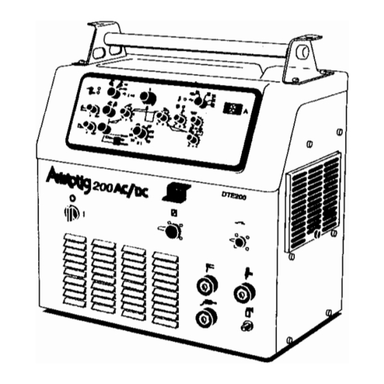
OPERATION General safety regulations for the handling of the equipment appear from page 68. Read through before you start using the equipment! Controls and connections Central connection Mains switch ON/OFF Mains voltage ON, LED Connection for remote control unit Welding voltage ON, LED Torch connector Error / Overheating, LED Connection for electrode holder (MMA) -
Page 71: Protection Against Overheating
This is also the value shown by the display on the DTE 255 prior to serial no. 844- - 950- - xxxx. For other DTE 255 machines and DTE 200 the value set by the remote control is shown by the display. - Page 72 Potentiometer, Hot Start time For setting and optimising the starting cycle with (R3) regard to the electrode size. TIG welding ( 10 - - 500 ms ) MMA welding (0.1 - - 2 s) Potentiometer, Arc Force For setting and optimising the Arc Force function (R9) (Anti Stick), for MMA welding only.
- Page 73 Position = MMA In this position the welding power source is prepared for welding with coated electrodes. The HF unit and the Lift- -Arc are disconnected, and the hot- - start function is activated in order to supply increased current at the start. Position = HF unit ON When pressing the torch trigger the gas starts flowing, the HF unit goes on, generating an...
-
Page 74: Mma Welding (Hand Welding Electrodes)
MMA welding (Hand welding electrodes) Adjusting the control panel for MMA welding Connect the welding and return cable to the OKC terminals D and F. Set switch (1) to the position for hand welding electrodes. If the machine is in MMA mode when the mains is switched on, there will be no open circuit voltage. -
Page 75: Tig Welding
TIG welding In TIG welding the torch trigger has three different functions: Two- -stroke. Four- - stroke. Four- -stroke with the possibility to shift between two currents (shift function). Adjusting the control panel for TIG welding Connect the welding cable and the respective return cable to the OKC terminals E and F, (for central connection: terminals F and P). - Page 76 (For MMA welding: 200 to 2000 ms.) 3. The start current is preset by the software to 10 A in the DTE 200 and 15 A in DTE 255. 4. The slope- -up time is adjusted on the front panel: 0 - - 10 s.
- Page 77 Setting direct and alternating current Direct current: Set switch (4) to the position for direct current with negative polarity. If pulsing has been selected: Set the pulse current value using potentiometer (8). Set the background current in per cent of the pulse current value using potentiometer (9).
-
Page 78: Maintenance
SPARE PARTS The spare parts lists are published in separate documents. Product filename / ordering no. DTE 200 0458 234 990 DTE 255 0457 784 990 - - 78 - - cdte1de2... -
Page 79: Notes
0301 035 881 DTE 255 with OKC connection for the TIG torch Spare parts are to be ordered through the nearest ESAB agency. Kindly indicate type of unit, serial number, denominations and ordering numbers according to the spare parts list. - Page 80 DTE 255 C = component designation in the circuit diagram Item Ordering no. Denomination Notes 0192 296 104 Knob 0191 508 102 Knob 0192 296 102 Knob 0468 543 882 Handle 0468 529 001 Rubber mat 0365 534 001 Sealing washer...
- Page 81 DTE 255 Edition 040621 - - 3 - - dpb1s...
- Page 82 DTE 255 C = component designation in the circuit diagram Item Ordering no. Denomination Notes Cover Replaced by item 202 0301 075 001 Screening box New design with built- -in cover, fits to all machines 0162 414 001 Insulating tube...
- Page 83 DTE 255 Edition 040621 - - 5 - - dpb1s...
- Page 84 DTE 255 C = component designation in the circuit diagram Item Ordering no. Denomination Notes 0367 268 001 HF unit AP13 0486 603 880 IGBT connection Safety circuit boards with connectors AP11, AP12 0486 613 880 Circuit board IGBT AP02...
- Page 85 DTE 255 Edition 040621 - - 7 - - dpb1s...
- Page 86 DTE 255 C = component designation in the circuit diagram Item Ordering no. Denomination Notes 0455 226 004 Spacer 0486 622 880 Circuit board AP09 0193 260 153 Connector 5- -pole XA, XB 0193 260 155 Connector 7- -pole 0486 829 880...
- Page 87 DTE 255 Edition 040621 - - 9 - - dpb1s...
- Page 88 DTE 255 Accessories Trolley (with room for gas bottle) ... . 0301 100 880 Return cable ......0369 857 888 Foot control FS 002 .
- Page 89 NOTES - - 79 - - notes...
- Page 90 ESAB subsidiaries and representative offices Europe NORWAY Asia/Pacific Representative offices AS ESAB AUSTRIA BULGARIA CHINA Larvik ESAB Ges.m.b.H ESAB Representative Office Shanghai ESAB A/P Tel: +47 33 12 10 00 Vienna- -Liesing Sofia Shanghai Fax: +47 33 11 52 03...
Need help?
Do you have a question about the DTE 255 and is the answer not in the manual?
Questions and answers