Table of Contents
Advertisement
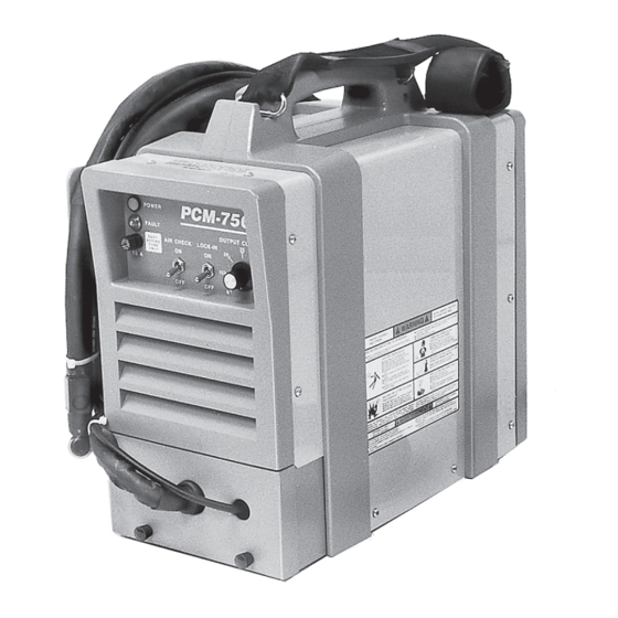
PLASMA ARC CUTTING PACKAGE
This manual provides installation and operation instructions for the following PCM-750i (Series A) cutting packages:
P/N 33980 - 230 V, 1-Phase
P/N 33982 - 460 V, 3-Phase
Starting with Serial No. PORI509000
These INSTRUCTIONS are for experienced operators. If you are not fully familiar with the principles of operation and
safe practices for electric welding equipment, we urge you to read our booklet, "Precautions and Safe Practices for
Arc Welding, Cutting, and Gouging," Form 52-529. Do NOT permit untrained persons to install, operate, or maintain
this equipment. Do NOT attempt to install or operate this equipment until you have read and fully understand these
instructions. If you do not fully understand these instructions, contact your supplier for further information. Be sure
to read the Safety Precautions before installing or operating this equipment.
Be sure this information reaches the operator.
You can get extra copies through your supplier.
INSTRUCTION MANUAL
PCM-750i
Series A
F-15-223-A
February, 1996
Advertisement
Table of Contents
Troubleshooting

Related Manuals for ESAB PCM-750i


Summary of Contents for ESAB PCM-750i
- Page 1 INSTRUCTION MANUAL PCM-750i PLASMA ARC CUTTING PACKAGE Series A This manual provides installation and operation instructions for the following PCM-750i (Series A) cutting packages: P/N 33980 - 230 V, 1-Phase P/N 33982 - 460 V, 3-Phase Starting with Serial No. PORI509000 These INSTRUCTIONS are for experienced operators.
-
Page 2: Table Of Contents
Location ......................Inspection ......................Primary Electrical Input Connections ..............SECTION 3 OPERATION ..................... 11 Operation ......................11 PCM-750i Controls .................... 11 Cutting with the PT-27 ..................11 Common Cutting Problems ................13 SECTION 4 MAINTENANCE ....................14 General ......................14 Inspection and Cleaning .................. -
Page 3: Safety Precautions
SAFETY PRECAUTIONS WARNING: hese Safety Precautions are for 5. Do not use equipment beyond its ratings. For example, your protection. They summarize precaution- overloaded welding cable can overheat and create a fire ary information from the references listed in hazard. Additional Safety Information section. - Page 4 EQUIPMENT MAINTENANCE -- Faulty or FUMES AND GASES -- Fumes and improperly maintained equipment can gases, can cause discomfort or harm, cause injury or death. Therefore: particularly in confined spaces. Do not breathe fumes and gases. Shield- 1. Always have qualified personnel perform the installa- ing gases can cause asphyxiation.
- Page 5 PRÉCAUTIONS DE SÉCURITÉ a. Éloigner suffisamment tous les matériaux combus- AVERTISSEMENT: Ces règles de sécurité ont pour objet tibles du secteur où l’on exécute des soudures ou des d’ assurer votre protection. Veillez à lire et à observer les coupes à l’arc, à moins de les recouvrir complètement précautions énoncées ci-dessous avant de monter l’...
- Page 6 52529 “Precautions and Safe Practices for Arc Weld- danger d’explosion; ce ventilateur ne fonctionne que ing, Cutting and Gouging” publié par ESAB. Nous conseillons également de consulter les publications si l’interrupteur correspondant du panneau avant se sui-vantes, tenues à...
-
Page 7: Description
1-1/4 inch thick. Refer to the following paragraphs for descrip- 1.3 PACKAGES AVAILABLE tions of the PCM-750i packages available as well as performance specifications. Table 1-1 lists PCM-750i packages available through your ESAB dealer. -
Page 8: Specifications
SECTION 1 DESCRIPTION 1.4 SPECIFICATIONS Refer to Tables 1-3, 1-4, and Figures 1-1 and 1-2 for PCM-750i technical specifications. Table 1-3. PCM-750i Specifications 40% Duty Cycle* 50 A @ 105 V dc Rated 60% Duty Cycle* 40 A @ 104 V dc... - Page 9 SECTION 1 DESCRIPTION Table 1-4. PT-27 Torch Specifications 7.3" (185 mm) Current Capacity (100% duty) 80 A DCSP Length of Service Llines 25 ft or 50 ft 3" (76 mm) Weight 25 ft 5.2 lbs (2.3 kg) 75° 1" (25.4 mm) 50 ft 9.6 lbs (4.4 kg) 1"...
-
Page 10: Installation
Adequate ventilation is necessary to provide proper for your input power supply. DO NOT connect a cooling of the PCM-750i and the amount of dirt, dust, and power source configured for 208/230 V to a 460 V excessive heat to which the equipment is exposed, input power supply. - Page 11 No. 12 CU/AWG 4-con- ductor wire (460 V, 3-phase) RECEPTACLE (P/N 674540) (supplied w/230 V consoles) COVER SAFETY INTERLOCK COVER WORK WORK CABLE SAFETY GROUND Allow at least 10 ft (3 m) between work and console Figure 2-1. PCM-750i Interconnection Diagram...
- Page 12 SECTION 2 INSTALLATION EARTH GROUND DO NOT ATTACH WORK CABLE TO PIECE BEING CUT WORK CABLE FREE GROUNDED WORK TABLE BE SURE WORK IS IN GOOD CONTACT WITH TABLE. EARTH GROUND WORK CABLE Figure 2-2. Ground and Work Cable Connections...
-
Page 13: Operation
270 volts. 3.3 CUTTING WITH THE PT-27 Use the following procedures to cut with the PT-27 torch Position the PCM-750i at least 10 feet (3 meters) from (Figure 3-4). the cutting area. Sparks and hot slag from the cut- ting operation can damage the unit. - Page 14 CONNECTION WORK CABLE TORCH GAS HOSE CONNECTION CONNECTION Figure 3-1. PCM-750i Controls For rapid re-starts, such as grate or heavy mesh NOTE cutting, do not release the torch switch. In the postflow mode, the arc can be re-started immedi- When replacing the nozzle, always inspect the elec- ately by depressing the torch switch.
-
Page 15: Common Cutting Problems
Damaged cutting nozzle. the probable cause of each. If problems are determined Loose cutting nozzle. to be caused by the PCM-750i, refer to the maintenance Heavy spatter. section of this manual. If the problem is not corrected after referring to the maintenance section, contact your Uneven Arc. -
Page 16: Maintenance
Use only recommended 4.3 PT-27 TORCH CONSUMABLE PARTS replacement parts. Make sure power switch on PCM-750i is in OFF Be sure that the wall disconnect switch or wall position before working on the torch. circuit breaker is open before attempting any in- spection or work inside of the PCM-750i. -
Page 17: Flow Switch
SECTION 4 MAINTENANCE The valve pin is a crucial member of the system. Its function is to open the gas flow check valve that is permanently assembled within the torch head. If the pin is not correctly placed in the electrode, the valve will not open and the system will not function. VALVE PIN DO NOT REVERSE. -
Page 18: Troubleshooting
SECTION 5 TROUBLESHOOTING The cause of control malfunctions can be found by 5.1 TROUBLESHOOTING referring to the sequence of operations and electrical schematic diagram (Figure 5-1) and checking the vari- ous components. A volt-ohmmeter will be necessary for some of these checks. ELECTRIC SHOCK CAN KILL! Be sure that all pri- mary power to the machine has been externally disconnected. - Page 19 SECTION 5 TROUBLESHOOTING No Air Is air hose connected? Connect Is air adjusted to 65 psig? Adjust Does air come on with air check switch? • No electrode in torch • No valve pin in torch • Replace electrode Check continuity of torch switch •...
-
Page 20: Section 5 Troubleshooting
Is air check switch OFF? Turn switch OFF Does arc start when nozzle contacts work without depressing torch switch? Check for short in torch switch Does air flow even when PCM-750i power switch is OFF? Replace Repair power solenoid valve... - Page 21 Is main 230 volt switch ON? Turn on main disconnect Is plug in receptacle? Insert plug in receptacle Is cooling fan turning? Replace pilot light Check voltage at receptacle and input power line Check main fuses Faulty power switch on PCM-750i...
-
Page 22: Section 5 Troubleshooting
Fault light will energize if voltage falls below 175 volts for 0.3 seconds or exceeds 260 volts even for an instant. The light will not turn OFF even when correct voltage is restored. Reset by placing PCM-750i power switch OFF and then ON again. - Page 23 SECTION 5 TROUBLESHOOTING 5.3 Sequence of Operation LOCK-IN "OFF" position PUSH RELEASE TORCH SWITCH OPEN CLOSE GAS SOLENOID VALVE 2 SEC. PREFLOW 10 SEC Postflow OPEN FLOW SWITCH CLOSE FAULT OVERLOAD LIGHT ENERGIZE HF CIRCUIT INVERTER CUTTING ARC (CURRENT) NOTES: When the torch switch is pushed during postflow period, the postflow and preflow times are canceled, and the HF is energized immediately.
- Page 24 SECTION 5 TROUBLESHOOTING LOCK-IN "ON" position PUSH RELEASE PUSH RELEASE TORCH SWITCH OPEN CLOSE GAS SOLENOID VALVE PREFLOW 2 SEC. 10 SEC Postflow POSTFLOW CLOSE OPEN FLOW SWITCH FAULT PILOT LIGHT ENERGIZE HF CIRCUIT INVERTER CUTTING ARC (CURRENT) NOTES: When the torch switch is pushed during postflow period, the postflow and preflow times are canceled, and the HF is energized immediately.
- Page 25 Figure 5-1. PCM-750i (Series A) Schematic Diagram (460 V, 3-Phase Input)
- Page 26 Figure 5-2. PCM-750i (Series A) Wiring Diagram (460 V, 3-Phase Input)
- Page 27 Figure 5-3. PCM-750i (Series A) Schematic Diagram (230 V, 1-Phase Input)
- Page 28 Figure 5-4. PCM-750i (Series A) Wiring Diagram (230 V, 1-Phase Input)
-
Page 29: Replacement Parts
The serial number is when ordering replacement parts. stamped on the unit nameplate. To order parts by phone, contact ESAB at 1-803-664- 6.2 ORDERING 5540 or 4460. Orders may also be faxed to 1-800-634- 7548. - Page 30 SECTION 6 REPLACEMENT PARTS 13,14 Figure 6-1. PCM-750i (Series A) Power Source (Front View) ITEM PART CIRCUIT REQ. DESCRIPTION SYMBOL 33953GY HOUSING, HANDLE & STRAP (LEFT) 34556GY HOUSING, HANDLE & STRAP (RIGHT) 951496 STRAP (HOOK 2-REQ’D: 951536) 32055GY CABINET, SILKSCREENED...
- Page 31 SECTION 6 REPLACEMENT PARTS REF 12 2,17 FIGURE 6-1 REF 5 FIGURE 6-6 18,19 VIEW A-A Figure 6-2. PCM-750i (Series A) Power Source (Right Side View) P/N 33980 - 230 V, 1-Phase ITEM PART CIRCUIT REQ. DESCRIPTION SYMBOL 32949YL COVER...
- Page 32 SECTION 6 REPLACEMENT PARTS REF 12 2,19 FIGURE 6-1 REF 5 FIGURE 6-6 21,20 VIEW A-A Figure 6-3. PCM-750i (Series A) Power Source (Right Side View) P/N 33982 - 460 V, 3-Phase ITEM PART CIRCUIT REQ. DESCRIPTION SYMBOL 32949YL COVER...
- Page 33 SECTION 6 REPLACEMENT PARTS 14 (PCB3) 14 (PCB2) REF 4 FIGURE 6-6 Figure 6-4. PCM-750i (Series A) Power Source (Left Side View) P/N 33980 - 230 V, 1-Phase ITEM PART CIRCUIT REQ. DESCRIPTION SYMBOL 951185 MODULE, DIODE, 100 A, 600 V, 100 NS (PAD-951518)
- Page 34 SECTION 6 REPLACEMENT PARTS REF 4 FIGURE 6-6 Figure 6-5. PCM-750i (Series A) Power Source (Left Side View) P/N 33982 - 460 V, 3-Phase ITEM PART CIRCUIT REQ. DESCRIPTION SYMBOL 951185 MODULE, DIODE, 100 A, 600 V, 100 NS (PAD-951518)
-
Page 35: Section 6 Replacement Parts
SECTION 6 REPLACEMENT PARTS Figure 6-6. PCM-750i (Series A) Power Source (Rear View) ITEM PART CIRCUIT REQ. DESCRIPTION SYMBOL 35903GY HOUSING, REGULATOR 33950GY HOUSING, REAR 33952GY HOUSING, WIRE WRAP/UTILITY BOX 58V75 ADAPTOR, BULKHEAD 951180 ON/OFF SWITCH, CIRC, BRKR., 50 A (230 V) 951181 ON/OFF SWITCH, CIRC. - Page 36 ESAB Welding & Cutting Products, Florence, SC Welding Equipment COMMUNICATION GUIDE - CUSTOMER SERVICES A. CUSTOMER SERVICE QUESTIONS: Telephone (803) 664-5540/Fax: (800) 634-7548 Order Entry Product Availability Pricing Hours: 8:30 AM to 5:00 PM EST Order Changes Saleable Goods Returns...
Need help?
Do you have a question about the PCM-750i and is the answer not in the manual?
Questions and answers