
Related Manuals for ESAB PCM-875A


Summary of Contents for ESAB PCM-875A
- Page 1 F-15-753 November, 2002 Installation, Operation and Maintenance Manual for the PCM-875A Plasmarc Mechanized Cutting System Cutting Systems 411 South Ebenezer Road Florence, South Carolina, U.S.A...
- Page 2 This manual is ESAB Part Number F15753 This manual is for the convenience and use of the cutting machine purchaser. It is not a contract or other obligation on the part of ESAB Cutting Systems. © ESAB Cutting Systems, 2002...
-
Page 3: Table Of Contents
1.8.1 National Standards................. 1.8.2 International Standards................12-16 Section 2 Description Page 2-(_) 2.1 General......................2.2 PCM-875A Power Console ................2.2.1 Technical Specifications – PCM-875A............. 2.2.2 Dimensions and Weight................2.3 Remote Arc Starter (RAS2)................2.3.1 Technical Specifications ................. 2.3.2 Dimensions and Weight................ - Page 4 3.4 Installing Front-end torch Parts ................ 15-17 3.5 Interconnecting Diagram ................. 18-19 Section 4 Operation Page 4-(_) 4.1 PCM-875A Console Operation -- General ............4.2 Console Controls.................... 4.3 RAS2 ......................4.4 PT-20AMX Plasma Torch................4.5 Cut Quality ..................... 4.5.1 Introduction ....................
- Page 5 PCM-875A System Table of Contents Section 5 Maintenance Page 5-(_) 5.1 PCM-875A Console ..................5.1.1 General ....................5.1.2 Inspection and Cleaning ................. 5.1.3 Flow Switch 5.2 RAS2 (Remote Arc Starter)................5.2.1 General ....................5.2.2 Spark Gap Procedure................5.3 PT-20AMX Plasmarc Torch ................
- Page 6 6.7 Remote Arc Starter Schematic................ Section 7 Replacement Parts Page 7-(_) 7.1 General ......................7.2 Ordering ......................7.3 PCM875A Power Console – 230V ..............7.4 PCM-875A Power Console – 400V ..............10-18 7.5 Remote Arc Starter..................19-21 7.6 PT-20AMX Plasmarc Cutting Torch..............22-25...
-
Page 7: Section 1 Safety
SECTION 1 SAFETY PCM-875A Mechanized Plasma Cutting System 1.1 Introduction The process of cutting metals with plasma equipment provides industry with a valuable and versatile tool. ESAB cutting machines are designed to provide both operation safety and efficiency. However, as with any machine tool,... -
Page 8: Safety Notations And Symbols
SECTION 1 SAFETY PCM-875A Mechanized Plasma Cutting System The following words and symbols are used 1.2 Safety Notations And Symbols throughout this manual. They indicate different levels of required safety involvement. ALERT or ATTENTION. Your safety is involved or potential equipment failure exists. -
Page 9: General Safety Information
SECTION 1 SAFETY PCM-875A Mechanized Plasma Cutting System 1.3 General Safety Information Some subjects listed are not related specifically to NOTICE the type of equipment covered in this manual. However, the safety principles still apply. They are offered as a reminder that this equipment or related apparatus should be operated with alertness and understanding. -
Page 10: Installation Precautions
SECTION 1 SAFETY PCM-875A Mechanized Plasma Cutting System Failure to follow safety warning label WARNING instructions could result in death or serious injury. Read and understand all safety warning labels on machine. Refer to operator’s manual for additional safety information. -
Page 11: Electrical Grounding
SECTION 1 SAFETY PCM-875A Mechanized Plasma Cutting System 1.5 Electrical Grounding Electrical grounding is imperative for proper machine operation and SAFETY. Refer to this manual’s Installation section for detailed grounding instructions. Electric shock hazard. WARNING Improper grounding can cause severe injury or death. - Page 12 SECTION 1 SAFETY PCM-875A Mechanized Plasma Cutting System Hazardous voltages. Electric shock WARNING can kill. · Do NOT touch plasma torch, cutting table or cable connections during plasma cutting process. · Always turn power off to plasma power supplies before touching or servicing plasma torch.
- Page 13 SECTION 1 SAFETY PCM-875A Mechanized Plasma Cutting System Radiation hazard. WARNING Arc rays can injure eyes and burn skin. · Wear correct eye and body protection. · Wear dark safety glasses or goggles with side shields. Refer to following chart for recommended...
- Page 14 SECTION 1 SAFETY PCM-875A Mechanized Plasma Cutting System Burn Hazard. WARNING Heat, spatter, and sparks cause fire and burns. · Do not cut near combustible material. · Do not have on your person any combustibles (e.g. butane lighter). · Pilot arc can cause burns. Keep torch nozzle away from yourself and others when activating plasma process.
-
Page 15: Service Precautions
SECTION 1 SAFETY PCM-875A Mechanized Plasma Cutting System 1.7 Service Precautions Hazardous voltages. Electric shock WARNING can kill. · Do NOT touch plasma torch, cutting table or cable connections during plasma cutting process. · Always turn power off to plasma power supplies before touching or servicing plasma torch. - Page 16 SECTION 1 SAFETY PCM-875A Mechanized Plasma Cutting System Danger of Electric Shock. DANGER Torch may be electrically active. Turn off Plasma Power Console before servicing torch. Establish and adhere to preventive maintenance. CAUTION A composite program can be established from recommended schedules.
-
Page 17: Safety References
Systems for Welding and Cutting” - NFPA 51, National Fire Protection Association. · “Safety Precautions for Oxygen, Nitrogen, Argon, Helium, Carbon Dioxide, Hydrogen, and Acetylene,” Form 3499. ESAB Cutting Systems. Obtainable through your ESAB representative or local distributor. · "Design and Installation of Oxygen Piping Systems," Form 5110. - Page 18 SECTION 1 SAFETY PCM-875A Mechanized Plasma Cutting System 1.8.2 International Accident Prevention VBG- Unfallverhütungsvorshriften General Provisions VBG 1 Allgemeine Unfallverhütungsvorshriften Electrical Equipment and operating Equipment VBG 4 Elektrische Anlagen Welding, Cutting and related working methods VBG 15 Schweißen un Schneiden un verwandte Verfahren...
- Page 19 SECTION 1 SAFETY PCM-875A Mechanized Plasma Cutting System VDE Regulations VDE - Vorschriften Erection of power installations with normal voltages up to 1000 volts VDE 0100 Bestimmungen für das Errichten von Stakstromanlagen mit Nennspannungen bis 1000 Volt Electrical equipment of industrial machines VDE0113 Elektrishe Ausrüstung von Industriemaschinen...
- Page 20 SECTION 1 SAFETY PCM-875A Mechanized Plasma Cutting System TRGS – Technische Richtlinien für Gefahrstoffe TRGS-102 Techn. Richtkonzentration (TRK) für gefährliche Stoffe Ermittlung u. Beurteilung der Konzentration gefährlicher TRGS-402 Stoffe in der Luft im Arbeitsbereich TRGS-900 Grenzwerte in der Luft am Arbeitsplatz (Luftgrenzwerte) TA-Luft un TA-Lärm (BLm SchV)
- Page 21 SECTION 1 SAFETY PCM-875A Mechanized Plasma Cutting System DIN EN ISO Harmonized Standards DIN EN ISO-Harmonisierte Normen Safety of machinery DIN EN 292/1 and 2 Sicherheit von Maschinen, Geräten und Anlagen Hoses for welding, cutting and allied processes DIN EN 559 Schläuche für Schweißen, Schneiden und verwandte...
- Page 22 SECTION 1 SAFETY PCM-875A Mechanized Plasma Cutting System Laser and laser related equipment DIN EN 31553 Laser und Laseranlagen Electrical equipment of machines DIN EN 60204-1 Elekrische Ausrüstung von Maschinen Radiation safety of laser products DIN EN 60825 Strahlensicherheit von Laseranlagen...
-
Page 23: Section 2 Description
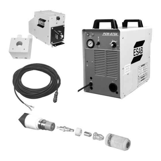
SECTION 2 Description PCM-875A Mechanized Plasma Cutting System 2.1 General The PCM-875A Mechanized Plasma Cutting System is a compact 60 ampere package consisting of plasma power console, remote arc starter, and PT-20AMX plasma torch. Simple bulkhead connections allow easy system assembly. - Page 24 SECTION 2 Description PCM-875A Mechanized Plasma Cutting System 2.2.2 Dimensions and Weight: PCM-875A Power Console 465 mm 516 mm 275 mm Weight = 39,5 kg...
-
Page 25: Dimensions And Weight
SECTION 2 Description PCM-875A Mechanized Plasma Cutting System 2.3 Remote Arc Starter (RAS-2) The remote arc starter (RAS-2) is placed inline between power console and torch. The RAS is the source of high frequency energy used to start the plasma cutting process. -
Page 26: Pt-20Amx Torch
SECTION 2 Description PCM-875A Mechanized Plasma Cutting System 2.4 PT-20AMX The patented PT-20AMX is a 100 amp capacity, pilot-arc mechanized torch available in 3 different torch lead length packages. The torch uses clean, dry air as the cut gas for cutting carbon steel, aluminum, or stainless steel. - Page 27 SECTION 2 Description PCM-875A Mechanized Plasma Cutting System 2.4.2 Dimensions 34,9 mm 435 mm...
-
Page 28: Torch Spare Parts Kit
SECTION 2 Description PCM-875A Mechanized Plasma Cutting System 2.4.3 Torch Spare Part Kit PT-20AMX Torch Spare Parts Kit is available for maintaining the PT-20AMX torch with minimum downtime. P/N 0558002319 P/Number Quantity Description 21326 Heat Shield (70/100 A) 21330 Cutting Nozzle (50 A) - Page 29 Read this entire manual before proceeding. Damage to property or equipment may occur. 3.2 Installation of the PCM-875A Power Console 3.2.1 Equipment Required A source of clean dry air at 153,4 liters/minute at 5,2 to 5,9 bar. The maximum inlet pressure of the air filter-regulator is 10,4 bar and should not be exceeded.
-
Page 30: Location
SECTION 3 Installation PCM-875A Mechanized Plasma Cutting System 3.2.2 Location Adequate ventilation is necessary to provide proper cooling of the PCM-875A. Exposure to dirt, dust and excessive heat should be minimized. There should be a minimum of 305 mm clearance... -
Page 31: Primary Electrical Input Connections
NOT connect a power console configured for 230V to a 460V input power. Damage to machine will occur. The PCM-875A Power Console is equipped with a 3 m 4 conductor power cable for 3- phase connection. If single-phase 230V is required, tape back red wire on the input power cable. -
Page 32: Connection Of Plasma Console To Cnc Interface
The chassis must be connected to an approved electrical ground. The PCM-875A power console is internally wired for connecting to an external power source. Console Power Lead 3.2.5 Connection of Plasma Console To CNC Interface The CNC interface (TB4) is mounted on the front left corner of the console base. -
Page 33: Secondary (Output) Connection
SECTION 3 Installation PCM-875A Mechanized Plasma Cutting System 3.2.6 Secondary (Output) Connections to Power Console Electric Shock Can Kill! WARNING Ensure all power is off by opening the line (wall) disconnect switch and power cord is disconnected before attempting to make any connections inside the power console. - Page 34 SECTION 3 Installation PCM-875A Mechanized Plasma Cutting System Pilot Arc Cut Gas Arc Current Bolt pilot arc cable ring connection to the copper terminal. Connect air hose to air/power connector (left hand threads). Connect power cable to air/power connector using...
- Page 35 SECTION 3 Installation PCM-875A Mechanized Plasma Cutting System Insert115VAC Pilot Arc Cable Insert 115VAC RAS cable through strain relief located in the lower right corner of the front panel. Rout 115VAC RAS cable along inside edge in notches in insulating material to TB1.
- Page 36 SECTION 3 Installation PCM-875A Mechanized Plasma Cutting System Remove connection for internal arc start from TB1 Plug terminal connectors into 2 available lugs on TB1. Cable Terminals to TB1 should be CAUTION insulated to prevent possible damage due to internal arcing in the power console.
-
Page 37: Mounting
SECTION 3 Installation PCM-875A Mechanized Plasma Cutting System 3.3 Connecting the Remote Arc Starter 3.3.1 Mounting RAS2 Mounting location of RAS unit is restricted by the length of torch leads, 1,2 m -- 5,4 m or 7,6 m. 228,6mm 12,7mm... -
Page 38: Connecting Service Lines (Input)
SECTION 3 Installation PCM-875A Mechanized Plasma Cutting System 3.3.2 Connecting Service Lines to Remote Arc Starter 2 Remove end covers on RAS2 box. 115 VAC Arc Start Cable Connector Pilot Arc Lug Air Connection Power Cable Lug · Connect arc start cable to RAS2 box. - Page 39 SECTION 3 Installation PCM-875A Mechanized Plasma Cutting System 3.3.3 Setting the Spark Gap in the RAS2 Factory set to 1mm. Adjustment procedure: 1. Loosen screw “a” using a 1/8” (0.125”) internal hex wrench. 2. Insert 1mm feeler gage between the tungsten electrodes.
-
Page 40: Ras2 Output Connections
SECTION 3 Installation PCM-875A Mechanized Plasma Cutting System 3.3.4 RAS2 Output Connections to Torch · Pilot Arc – Connect pilot arc cable in torch bundle to pilot arc output lug using #10 screw, lock washers and nut. · Torch – left hand threads connect the torch gas (air) and plasma arc current. - Page 41 SECTION 3 Installation PCM-875A Mechanized Plasma Cutting System 3.3.5 Terminating Shield Braid at RAS2 1. Insert Braid and hose bundle through RAS cover hole. Insert bundle 2. Flare braid by bending it back at 90 degrees about 25 mm from the end.
- Page 42 SECTION 3 Installation PCM-875A Mechanized Plasma Cutting System 3. Insert ground plate over torch leads. Insert Ground Plate 4. Fasten ground plate with 4 screws inserted from the outside. Trim braid strands if desired. Fasten Ground Plate 3-14...
-
Page 43: Installing Front-End Torch Parts
SECTION 3 Installation PCM-875A Mechanized Plasma Cutting System 3.4.1 Installing Torch Front End Parts Make sure power switch on console is in WARNING OFF position and primary input power is de-energized. 1. The seat comes assembled to the front end Seat of the torch. - Page 44 SECTION 3 Installation PCM-875A Mechanized Plasma Cutting System 3. Install the electrode insulator (21373) onto electrode holder assembly (21332) and then thread electrode (21150) onto the electrode holder assembly. Assemble electrode firmly by hand. Do not use wrenches or pliers. These three parts combined are the electrode assembly.
-
Page 45: Section 3 Installation
SECTION 3 Installation PCM-875A Mechanized Plasma Cutting System 6.Tighten heat shield fully to hold the parts in firm contact with each other and to the torch head. “Fully” means at least 5mm rotation after electrode seat contacts electrode holder. 7. After retainer/heat shield is tightened, try to rotate the nozzle with your finger tips. -
Page 46: Interconnecting Diagram
SECTION 3 Installation PCM-875A Mechanized Plasma Cutting System 3.5 Interconnecting Diagram 3-18... - Page 47 SECTION 3 Installation PCM-875A Mechanized Plasma Cutting System Air Supply Wall Disconnect Switch (Grounded) PCM-875A Power Supply Cable Work Cable (Negative) Pilot Arc Cable Gas Connection Power Supply Cable 115 V High Frequency Start Cable RAS Input Bulkhead Remote Arc Starter...
- Page 48 SECTION 3 Installation PCM-875A Mechanized Plasma Cutting System This page intentionally left blank. 3-20...
-
Page 49: Section 4 Operation
Noise Levels May Exceed Safe WARNING Limits. Sparks and Slag May Be Hazardous. · Wear Safety Approved Hearing Protection. · Wear Safety Approved Eye Protection. Possible Damage to Console from CAUTION Sparks and Slag. Position PCM-875A at least 3 meters form the Cutting Area. -
Page 50: Console Controls
SECTION 4 Operation PCM-875A Mechanized Plasma Cutting System 4.2 PCM-875A Plasma Console Controls Power Switch -- Rear Panel · Located on the rear panel. · On Position – Front panel green pilot light will glow indication control circuit is energized and cooling fan will run. - Page 51 SECTION 4 Operation PCM-875A Mechanized Plasma Cutting System Fault Light – Operations are stopped. Will illuminate amber under the following conditions: · Light mostly ON but will blink off 1/10 of a second every second. Indicates airflow is low. ·...
-
Page 52: Ras2
SECTION 4 Operation PCM-875A Mechanized Plasma Cutting System 4.4 PT-20AMX Plasma Torch. Electric Shock Can Kill! WARNING Plasma incorporates high voltages at dangerous amperage. Do not touch the; · Plasma torch · Torch lead · RAS · RAS supply lines ·... -
Page 53: Cut Quality
SECTION 4 Operation PCM-875A Mechanized Plasma Cutting System 4.5 Cut Quality 4.5.1 Introduction Causes affecting cut quality are interdependent. Changing one variable affects all others. Determining a solution may be difficult. The following guide offers possible solutions to undesirable cutting results. To begin select the most prominent condition: §... -
Page 54: Cut Angle
SECTION 4 Operation PCM-875A Mechanized Plasma Cutting System 4.5.2 Cut Angle Negative Cut Angle Top dimension is greater than the bottom. Part · Misaligned torch · Bent or warped material · Worn or damaged consumables · Standoff low (arc voltage) ·... -
Page 55: Cut Flatness
SECTION 4 Operation PCM-875A Mechanized Plasma Cutting System 4.5.3 Cut Flatness Top And Bottom Rounded Condition usually occurs when material is 0.25" thick (6,4mm) or less. · High current for given material thickness (See process data for proper settings). Drop... -
Page 56: Surface Finish (Roughness)
SECTION 4 Operation PCM-875A Mechanized Plasma Cutting System 4.5.4 Surface Finish Process Induced Roughness Cut face is consistently rough and may be confined to one axis. · Worn or damaged consumables Top View Cut Face Machine Induced Roughness Can be difficult to distinguish from process induced roughness and is often confined to one axis. -
Page 57: Dross
SECTION 4 Operation PCM-875A Mechanized Plasma Cutting System 4.5.5 Dross Dross is a by-product of the cutting process. It is the undesirable material that remains attached to the part. In most cases, dross can be reduced or eliminated with proper torch and cutting parameter setup. Refer to Process Data. - Page 58 SECTION 4 Operation PCM-875A Mechanized Plasma Cutting System Side View Splatter Top Dross Appears as splatter on top of material. Usually removes easily. · Cutting speed fast · Standoff high (arc voltage). Cut Face Intermittent Dross Appears on top or bottom along kerf.
-
Page 59: Dimensional Accuracy
SECTION 4 Operation PCM-875A Mechanized Plasma Cutting System 4.5.6 Dimensional Accuracy Generally, using the slowest possible speed (within approved levels) will optimize part accuracy. Most material thickness overlap for different voltages. Select consumables to allow a lower arc voltage and slower cutting speed. - Page 60 SECTION 4 Operation PCM-875A Mechanized Plasma Cutting System Mild Steel Material: PT-20AMX Amperes: Plasmarc Torch Gas: Lock Ring P/N 57N70 Handle with Sleeve 05508003419 Torch Body P/N 21359 Electrode Holder P/N 21332 Assembly Electrode P/N 21373 Insulator Electrode 50Hz 0558001617...
-
Page 61: Process Data
SECTION 4 Operation PCM-875A Mechanized Plasma Cutting System PT-20AMX Amperes Process Data Mild Steel Material Thickness Air Pressure Height Readings Initial Height Arc Voltage (Stand-off) Travel Speed mm per minute 3810 2540 Kerf Width Millimeters 4-13... - Page 62 SECTION 4 Operation PCM-875A Mechanized Plasma Cutting System Mild Steel Material: PT-20AMX Amperes: Plasmarc Torch Gas: Lock Ring P/N 57N70 Handle with Sleeve 05508003419 Torch Body P/N 21359 Electrode Holder P/N 21332 Assembly Electrode P/N 21373 Insulator Electrode 50Hz 0558001617...
-
Page 63: Travel Speed
SECTION 4 Operation PCM-875A Mechanized Plasma Cutting System PT-20AMX Amperes Process Data Mild Steel Material Thickness 10,0 13,0 Air Pressure Height Readings Initial Height Arc Voltage (Stand-off) Travel Speed mm per minute 2540 1651 1016 Kerf Width Millimeters 4-15... - Page 64 SECTION 4 Operation PCM-875A Mechanized Plasma Cutting System Aluminum Material: PT-20AMX Amperes: Plasmarc Torch Gas: Lock Ring P/N 57N70 Handle with Sleeve 05508003419 Torch Body P/N 21359 Electrode Holder P/N 21332 Assembly Electrode P/N 21373 Insulator Electrode 50Hz 0558001617 Nozzle 50A P/N 21330 Heat Shield –...
- Page 65 SECTION 4 Operation PCM-875A Mechanized Plasma Cutting System PT-20AMX Amperes Process Data Aluminum Material Thickness Air Pressure Height Readings Initial Height Arc Voltage (Stand-off) Travel Speed mm per minute 3810 2667 Kerf Width Millimeters 1,57 1,57 4-17...
- Page 66 SECTION 4 Operation PCM-875A Mechanized Plasma Cutting System Aluminum Material: PT-20AMX Amperes: Plasmarc Torch Gas: Lock Ring P/N 57N70 Handle with Sleeve 05508003419 Torch Body P/N 21359 Electrode Holder P/N 21332 Assembly Electrode P/N 21373 Insulator Electrode 50Hz 0558001617 Nozzle 50A P/N 21330 Heat Shield –...
- Page 67 SECTION 4 Operation PCM-875A Mechanized Plasma Cutting System PT-20AMX Amperes Process Data Aluminum Material Thickness 10,0 13,0 Air Pressure Height Readings Initial Height Arc Voltage (Stand-off) Travel Speed mm per minute 2286 1905 Kerf Width Millimeters Available 4-19...
- Page 68 SECTION 4 Operation PCM-875A Mechanized Plasma Cutting System Material: Stainless Steel PT-20AMX Amperes: Plasmarc Torch Gas: Lock Ring P/N 57N70 Handle with Sleeve 05508003419 Torch Body P/N 21359 Electrode Holder P/N 21332 Assembly Electrode P/N 21373 Insulator Electrode 50Hz 0558001617...
- Page 69 SECTION 4 Operation PCM-875A Mechanized Plasma Cutting System PT-20AMX Amperes Process Data Stainless Steel Material Thickness Air Pressure Height Readings Initial Height Arc Voltage (Stand-off) Travel Speed mm per minute 3302 1905 Kerf Width Millimeters Available 4-21...
-
Page 70: Stainless Steel
SECTION 4 Operation PCM-875A Mechanized Plasma Cutting System Material: Stainless Steel PT-20AMX Amperes: Plasmarc Torch Gas: Lock Ring P/N 57N70 Handle with Sleeve 05508003419 Torch Body P/N 21359 Electrode Holder P/N 21332 Assembly Electrode P/N 21373 Insulator Electrode 50Hz 0558001617... - Page 71 SECTION 4 Operation PCM-875A Mechanized Plasma Cutting System PT-20AMX Amperes Process Data Stainless Steel Material Thickness 10,0 13,0 Air Pressure Height Readings Initial Height Arc Voltage (Stand-off) Travel Speed mm per minute 1270 Kerf Width Millimeters available 4-23...
- Page 72 SECTION 4 Operation PCM-875A Mechanized Plasma Cutting System This page intentionally left blank. 4-24...
-
Page 73: Section 5 Maintenance
Do not permit untrained persons to CAUTION inspect, clean, or repair this equipment. Maintenance must be performed by specially trained personnel. Use of replacement parts other than ESAB NOTICE replacement parts may void warranty. Electric Shock Can Kill! WARNING Disconnect wall switch before inspection... -
Page 74: Inspection And Cleaning
SECTION 5 Maintenance PCM-875A Plasmarc Cutting System 5.1.2 Inspection and Cleaning Frequent inspection and cleaning of the PCM 875A system is recommended for safe and proper operation. A. Check work cable for secure connection to workpiece. B. Check safety earth ground at workpiece and at power console chassis. - Page 75 SECTION 5 Maintenance PCM-875A Plasmarc Cutting System Water and oil may accumulate in CAUTION compressed air lines. Direct the first air blast away from equipment to avoid possible damage. G. With all input power disconnected, wearing proper eye and face protection, blow out the inside of the console using low-pressure dry compressed air.
-
Page 76: Flow Switch
SECTION 5 Maintenance PCM-875A Plasmarc Cutting System 5.1.3 Flow Switch The Flow Switch (P/N 951202) may need to be cleaned if excessive contamination is found in the air supply. View A-A Flow Switch Location Note: The flow switch can be disassembled and cleaned without extraction from the power supply. -
Page 77: General
SECTION 5 Maintenance PCM-875A Plasmarc Cutting System 5.2. Remote Arc Starter 5.2.1 General Check input and output bulkhead connections for tightness. 5.2.2 Spark Gap Factory set to 1mm. Adjustment procedure: 1. Loosen screw “a” using a 1/8” (0.125”) internal hex wrench. -
Page 78: Pt-20Amx Plasmarc Torch
SECTION 5 Maintenance PCM-875A Plasmarc Cutting System 5.3 PT-20AMX Plasmarc Torch Before any maintenance is attempted on WARNING this torch, make sure the POWER SWITCH on the console is in the OFF position and the PRIMARY INPUT POWER is DE-ENERGIZED. -
Page 79: Dirt Or Contamination
SECTION 5 Maintenance PCM-875A Plasmarc Cutting System 5.3.2 Dirt or Contamination Dirt or other contamination in the torch and loose consumable parts can cause premature failure of the PT-20AM Torch through internal arcing. To avoid this, users are instructed to do the following: 1. -
Page 80: Consumables- Remove And Replace
SECTION 5 Maintenance PCM-875A Plasmarc Cutting System The torch requires good electrical contact CAUTION between the electrode seat and electrode holder. If good contact is not maintained, then the resulting potential difference causes internal arcing and possible torch damage. 5.3.4 Damage Caused by Loose Parts and Torch Overheating. - Page 81 SECTION 5 Maintenance PCM-875A Plasmarc Cutting System 3. Remove the nozzle and electrode assembly from the shield and inspect for wear. The nozzle orifice should be round at both the entrance and the exit. If the nozzle orifice is worn in an oval shape or shows other signs of damage at either end, it should be replaced.
-
Page 82: Measuring Torch Gas Flows
SECTION 5 Maintenance PCM-875A Plasmarc Cutting System 5. Inspect the o-ring on the torch. If it shows signs of wear or damage, replace it. If it is dry, lubricate it with a thin film of lubricant supplied with spare parts kit Inspect o-ring of torch 6. -
Page 83: Removal And Replacement Of The Torch Body
SECTION 5 Maintenance PCM-875A Plasmarc Cutting System 5.3.7 Removal and Replacement of the Torch Body Make sure that the power source has been WARNING turned off and that the power cable has been unplugged at the wall receptacle before proceeding. - Page 84 SECTION 5 Maintenance PCM-875A Plasmarc Cutting System This page intentionally left blank 5-12...
-
Page 85: Section 6 Troubleshooting
SECTION 6 Troubleshooting PCM-875A Plasmarc System 6.1 Troubleshooting PCM-875A Plasmarc System Electric Shock Can Kill! WARNING Ensure that all primary power to the machine has been externally disconnected. Open the line disconnect switch or circuit breaker before inspection, maintenance or repair inside power console. -
Page 86: Power Light (Pl1) Does Not Come On
SECTION 6 Troubleshooting PCM-875A Plasmarc System 6.2 Troubleshooting guide for PCM-875A Plasmarc System 6.2.1 Power Light (PL1) does not come on · Visually inspect the machine for damage. · Check if the cooling fan is running. If not running, check the following: §... -
Page 87: Troubleshooting
SECTION 6 Troubleshooting PCM-875A Plasmarc System 6.2.3 The Power light is on, but nothing happens when the torch is signaled to fire. Fault light does not activate. NOTE: Unplug high frequency connection before attempting to work on this problem. ·... - Page 88 SECTION 6 Troubleshooting PCM-875A Plasmarc System 6.2.4 Fault light activates when torch is signaled to fire The Fault circuit is used to monitor conditions necessary for the safe operation of the PCM-875. The fault light will glow amber under the following conditions and operations will come to a complete stop: ·...
- Page 89 SECTION 6 Troubleshooting PCM-875A Plasmarc System Fault light activates (continued) · Over Temperature. The fault light will be mostly off but will blink on for 1/10 of a second, every second. This generally indicates that the duty cycle has been exceeded.
- Page 90 SECTION 6 Troubleshooting PCM-875A Plasmarc System 6.2.5 Air is On but nothing happens when torch is signaled to fire. · Check pilot arc fuse located on rear panel. If it is open, nothing will happen when torch switch is depressed.
-
Page 91: Poor Cutting Performance
SECTION 6 Troubleshooting PCM-875A Plasmarc System 6.2.6 High Frequency and Pilot Arc are on but Main Arc does not transfer. · Make sure work clamp is connected to work material. · Check the torch. Replace consumables if necessary. · Make sure the current setting potentiometer is set above 10 amps. -
Page 92: Main Arc Difficult To Start
SECTION 6 Troubleshooting PCM-875A Plasmarc System 6.2.9 Main arc is difficult to start. · The most common reason is worn or missing consumables. Check and replace if necessary. · Input air must be clean and dry. · Input air pressure must be between 65 - 75 psig. -
Page 93: Reference Voltage Checks
SECTION 6 Troubleshooting PCM-875A Plasmarc System Reference Voltage Checks A. Control Board Assembly (PCB1) LED’s LED-1 Torch Switch LED-2 High Frequency LED-3 Gas Solenoid Valve Voltage Test Points Tests are made with power on - no arc. Disable High Frequency by disconnecting blue wire... -
Page 94: Pt-20Amx Torch Troubleshooting10
SECTION 6 Troubleshooting PCM-875A Plasmarc System 6.4 PT-20AMX Torch Troubleshooting Common Cutting Problems Listed below are common cutting problems followed by the probable cause of each. If problems are determined to be caused by the PCM-875, refer to the maintenance section of this manual. -
Page 95: Double Arcing
SECTION 6 Troubleshooting PCM-875A Plasmarc System 6.4.4 Double Arcing · .Damaged Nozzle Orifice. · Low air pressure. · Damaged cutting nozzle. · Loose cutting nozzle. · Heavy spatter accumulation on nozzle. 6.4.5 Uneven Arc. · Damaged cutting nozzle or worn electrode. -
Page 96: Power Console Electrical Drawings
SECTION 6 Troubleshooting PCM-875A Plasmarc System 6.5 230V Power Console Electrical Drawings 6.5.1 230V Console Schematic Part 1 208/230 VAC 230V 50/60 HZ TB5-1 3 PH CE 208V TB5-2 208V 230V 400V LINE LOAD 275V 275V X11 X12 3A,600VAC 275V... - Page 97 SECTION 6 Troubleshooting PCM-875A Plasmarc System 230V Schematic Part 2 TB4-1 ARC ON (SEE CHART) SIGNAL TO CNC TB4-2 TB4-3 START SIGNAL TB4-4 FROM CNC TB4-5 VOLTAGE DIVIDER TB4-6 SIGNAL TO CNC P2-3 P2-4 P1-12 P1-11 P6-1 P6-2 P2-2 75mA...
- Page 98 SECTION 6 Troubleshooting PCM-875A Plasmarc System 6.5.2 230V Power Console Wiring Diagrams Part 1 J1 SHIELD GND 2 P5-1 P5-2 PCB1 (SEE CHART) S1-T3 BLK IBR-T BLK 7 6 5 S1-T2 BLK IBR-S BLK CE MARKED UNITS IBR-R BLK PCB5 P1-3 VIO...
- Page 99 SECTION 6 Troubleshooting PCM-875A Plasmarc System 230V Power Console Wiring Diagrams Part 2 DETAIL "A" (PCB1) TS1-1 T2-X7 J1-1 CLR (TP) S2-1 TS1-2 SOL1-1 J1-2 BLK (TP) S2-2 T2-X9 SOL1-2 T2-X1 T2-X10 S1-3 T2-X2 T2-X5 T2-X8 PL2-(+) 5 PCB1 P6-6 WHT...
- Page 100 SECTION 6 Troubleshooting PCM-875A Plasmarc System 230V Power Console Wiring Diagrams Part 3 PCB5 PCB4 GND 5 (SHUNT) VIEW B-B VIEW E-E PCB1-P4 PCB1- P3 1 2 3 R2-1 RED R15-2 RED L2-X1 PCB1 P5-2 BLK(TP) PCB1 P5-1 CLR(TP) PCB2...
- Page 101 SECTION 6 Troubleshooting PCM-875A Plasmarc System 230V Power Console Wiring Diagrams Part 4 PCB4-2 BLU K1-T3 YEL PCB1 P5-9 GRY VIEW F-F T5-H2 BLK PCB1 P2-14 VIO PCB1 P5-3 YEL PCB1 P2-13 BLU PCB1 P5-4 YEL TB5-2 GRY PCB1 P2-11 VIO...
-
Page 102: Power Console Electrical Drawings
SECTION 6 Troubleshooting PCM-875A Plasmarc System 6.6 400V Power Console Electrical Drawings 6.6.1 400V Console Schematic Part 1 230V 400V H4 460V EMC FILTER P/N-952253 510V 510V X9 X10 400 VAC 50/60 HZ 3 PH 3A,600VAC 510V 115V 10,50W P2-7 0.22UF,1KV... - Page 103 SECTION 6 Troubleshooting PCM-875A Plasmarc System 400V Console Schematic Part 2 (SEE CHART) TB4-1 ARC ON TB4-2 SIGNAL TO CNC TB4-3 START SIGNAL TB4-4 FROM CNC TB4-5 VOLTAGE DIVIDER TB4-6 SIGNAL TO CNC P2-3 P2-4 P1-12 P1-11 P6-1 P6-2 P2-2...
- Page 104 SECTION 6 Troubleshooting PCM-875A Plasmarc System 6.6.2 400V Console Wiring Diagrams Part 1 J1 SHIELD GND 2 P5-1 P5-2 PCB1 (SEE CHART) S1-T3 IBR-T BLK S1-T2 IBR-S BLK CE MARKED UNITS IBR-R BLK S1-T1 ONLY PCB5 P1-3 VIO PCB1 P6-7 YEL...
- Page 105 SECTION 6 Troubleshooting PCM-875A Plasmarc System 400V Console Wiring Diagrams Part 2 DETAIL "A" (PCB1) TS1-1 T2-X1 J1-1 CLR (TP) S2-1 TS1-2 SOL1-1 J1-2 BLK (TP) S2-2 T2-X3 SOL1-2 T2-X9 T2-X4 S1-3 T2-X10 T2-X5 T2-X2 PL2-(+) PCB1 P6-6 T2-X6 S1-2...
- Page 106 SECTION 6 Troubleshooting PCM-875A Plasmarc System 400V Console Wiring Diagrams Part 3 PCB5 PCB4 GND 5 (SHUNT) VIEW B-B VIEW E-E 3 4 5 T2-H3 BLU PCB1-P3 PCB1-P4 FASTON TERMINAL PINK FEMALE C4-2 YEL R2-1 RED R15-2 BLK P/N A-950906...
- Page 107 SECTION 6 Troubleshooting PCM-875A Plasmarc System 400V Console Wiring Diagrams Part 4 PCB1 P1-9 WHT PCB1 P1-10 WHT PCB1 P1-6 BLU PCB1 P5-3 YEL PCB1 P1-5 BLU PCB1 P5-4 YEL X7 X8 X9 PCB4-2 BLU K1-T3 YEL BOTTOM PCB1 P5-9 GRY...
-
Page 108: Remote Arc Starter Schematic
SECTION 6 Troubleshooting PCM-875A Plasmarc System 6.7 Remote Arc Starter (RAS-2) Schematic C1, C2 2500 pF STEP UP FILTER TRANSFORMER SPARK GAP 0.040 POWER SUPPLY (-) TORCH (-) PCB1 REACTOR FILTER PILOT ARC IN PILOT ARC TO TORCH 6-24... -
Page 109: Section 7 Replacement Parts
7.2 Ordering To ensure proper operation, it is recommended that only genuine ESAB parts and products be used with this equipment. The use of non-ESAB parts may void your warranty. Replacement parts may be ordered from your... - Page 110 SECTION 7 Replacement Parts 7.3 PCM-875A Power Console – 230V- (P/N 0558003356) PCM-875A POWER FAULT CURRENT CONTROL PRESSURE TEST TEST OPERATE TORCH WORK...
-
Page 111: Replacement Parts
SECTION 7 Replacement Parts Ref. Part Number Quantity Description Elect. 951754 Lamp, LED Yellow, 12V 0558001176 POT, 10K, 30W 951526 Lamp, Neon, White 21711 Gauge, 1.5 160 PSI WHT CDM STL 634518 Toggle Switch, 2 pos, 15A, 125V Not Required when Reactor Assembly Reference Only RAS-2 is used 182W12... -
Page 112: Pcm875A Power Console - 230V
SECTION 7 Replacement Parts PCM-875A Power Console – 230V- (P/N 0558003356) 230V CE... - Page 113 SECTION 7 Replacement Parts Ref. Part Number Quantity Description Elect. 951182 Axial Fan, AC 17240310 Resistor, 10K, 25W R2,15 952233 Output Inductor 2091558 Label Label 952026 Term block, 7 pos, 25A, 12-18AWG 951202 Switch, Flow, .25 GPN, SPST 952597 Filter EMC, 250.440V 3ph 950249 Valve, Solenoid, ¼...
- Page 114 SECTION 7 Replacement Parts PCM-875A Power Console – 230V- (P/N 0558003356) Top View-and Right Side...
- Page 115 SECTION 7 Replacement Parts Ref. Part Number Quantity Description Elect. 951340 Plug Female, 14 pos, PCB1 951339 Plug Female, 12 pos, PCB1 38214 PCB Control PCB1 951339 Plug Female, 12 pos, PCB1 951340 Plug Female, 14 pos, PCB1 38131 PCB Startup PCB5 31488 PCB Ay, Shunt Board...
- Page 116 SECTION 7 Replacement Parts PCM-875A Power Console – 230V- (P/N 0558003356) Left Side 230V CE Detail...
- Page 117 SECTION 7 Replacement Parts Ref. Part Number Quantity Description Elect. 36822 Hose, Assy, B/A-WX1/4NPT Rub 0558001177 PCB Assy, Mosfet/IGBT Driver Bd PCB2,3 952237 Capacitor, 1800uf, 400VDC, W/nut C1,2 90858003 .75FT Tubing, Plas, .25 od X .04 W BLK 950487 Terminal Block, 2 pos, 20A 952235 Module, Input bridge/scr 951205...
- Page 118 SECTION 7 Replacement Parts 7.4 PCM-875A Power Console – 400V- (P/N 0558003357) PCM-875A POWER FAULT CURRENT CONTROL TEST PRESSURE TEST OPERATE TORCH WORK 7-10...
- Page 119 SECTION 7 Replacement Parts Ref. Part Number Quantity Description Elect. 951754 Lamp, LED Yellow, 12V 0558001176 POT, 10K, 30W 951526 Lamp, Neon, White 21711 Gauge, 1.5 160 PSI WHT CDM STL 634518 Toggle Switch, 2 pos, 15A, 125V Not Required when Reactor Assembly Reference Only RAS-2 is used 182W12...
-
Page 120: Pcm-875A Power Console - 400V
SECTION 7 Replacement Parts PCM-875A Power Console – 400V- (P/N 0558003357) 400V CE 7-12... - Page 121 SECTION 7 Replacement Parts Ref. Part Number Quantity Description Elect. 951182 Axial Fan, AC 17240310 Resistor, 10K, 25W R2,15 952233 Output Inductor 952026 Term block, 7 pos, 25A, 12-18AWG 951202 Switch, Flow, .25 GPN, SPST 952253 Filter, EMC, 400V 950249 Valve, Solenoid, ¼...
- Page 122 SECTION 7 Replacement Parts PCM-875A Power Console – 400V- (P/N 0558003357) 7-14...
- Page 123 SECTION 7 Replacement Parts Ref. Part Number Quantity Description Elect. 951340 Plug Female, 14 pos, PCB1 951339 Plug Female, 12 pos, PCB1 38214 PCB Control PCB1 951339 Plug Female, 12 pos, PCB1 951340 Plug Female, 14 pos, PCB1 38131 PCB Startup PCB5 31488 PCB Ay, Shunt Board...
- Page 124 SECTION 7 Replacement Parts PCM-875A Power Console – 400V- (P/N 0558003357) 400V CE 13 14 7-16...
- Page 125 SECTION 7 Replacement Parts Ref. Part Number Quantity Description Elect. 36822 Hose, Assy, B/A-WX1/4NPT Rub 0558001178 PCB Assy, IGBT Driver Bd PCB2 952237 Capacitor, 1800uf, 400VDC, W/nut C1,2 90858003 .75FT Tubing, Plas, .25 od X .04 W BLK 950487 Terminal Block, 2 pos, 20A 952235 Module, Input bridge/scr 17750010...
-
Page 126: Remote Arc Starter
SECTION 7 Replacement Parts 7.5 Remote Arc Starter (RAS-2) (P/N 0558003670) View B-B View A-A 7-18... - Page 127 SECTION 7 Replacement Parts Ref. Part Number Quantity Description Elect. 674969 PC Board Filter PCB1 634090 Adapt ¼ NPTM C/A W*F Cable 0558003679 Reactor Assembly H.F. Reference Screw, PHTF #10-32 X .38 inch 7-19...
- Page 128 SECTION 7 Replacement Parts Remote Arc Starter (RAS-2) (P/N 0558003670) REF. 9 10 7-20...
- Page 129 SECTION 7 Replacement Parts Ref. Part Number Quantity Description Elect. 37410 Cable Assembly, Arc Starter, 15,2m 37411 Cable Assembly, Arc Starter, 30,4m 0558003692 Hose Air/Oxy ¼ NPTF RAS2, 15,4m 0558003693 Hose Air/Oxy ¼ NPTF RAS2, 30,4m 0558003686 Cable, Pilot Arc, RAS2, 15,2m 0558003687 Cable, Pilot Arc, RAS2, 30,4m 37341...
-
Page 130: Pt-20Amx Plasmarc Cutting Torch
SECTION 7 Replacement Parts 7.6 PT-20AMX Plasmarc Cutting Torch 7-22... - Page 131 SECTION 7 Replacement Parts PT-20 AMX Plasma Torch with Coaxial Pilot Arc Cable With 4 ft. torch leads, without handle rack P/N 0558002632 With 17 ft. torch leads, without handle rack P/N 0558002633 With 25 ft. torch leads, without handle rack P/N 0558003381 Ref.
- Page 132 SECTION 7 Replacement Parts PT-20 AMX Front End and Spare Parts Kit 7-24...
- Page 133 The description of the heat shield (P/N 21326) NOTICE listed above indicates a range of 70 to 100 amperes. The PCM-875A is capable of a maximum of 60 amperes (60% duty cycle). Testing has proven satisfactory results when using this heat shield at 60 amps and lower.
- Page 134 SECTION 7 Replacement Parts This page intentionally left blank. 7-26...
- Page 135 See back of Title Page for revision list.
- Page 136 Customer // Technical Support (843) 664-4405 (800) ESAB-123 (372-2123) ESAB Welding and Cutting Products PO BOX 100545 Ebenezer Road Florence, SC 29501-0545 http://www.esab.com ESAB Cutting Systems – Canada 6010 Tomken Road Mississauga, Ontario Canada L5T 1X9 Phone: (905) 670-0220 Fax: (905) 670-4879...
Need help?
Do you have a question about the PCM-875A and is the answer not in the manual?
Questions and answers