Table of Contents
Advertisement
P/N 36975 - 208-230/460 Vac 3-phase, 230 Vac 1-phase, 60 Hz
P/N 36977 - 400/440 Vac 3-phase 50/60 Hz
P/N 36976 - 575 Vac 3-phase, 60 Hz
These INSTRUCTIONS are for experienced operators. If you are not fully familiar with the principles of operation and safe
practices for arc welding equipment, we urge you to read our booklet, "Precautions and Safe Practices for Arc Welding, Cutting,
and Gouging", Form 52-529. Do NOT permit untrained persons to install, operate, or maintain this equipment. Do NOT attempt
to install or operate this equipment until you have read and fully understand these instructions. If you do not fully understand
these instructions, contact your supplier for further information. Be sure to read the Safety Precautions before installing or
operating this equipment.
Be sure this information reaches the operator.
You can get extra copies through your supplier.
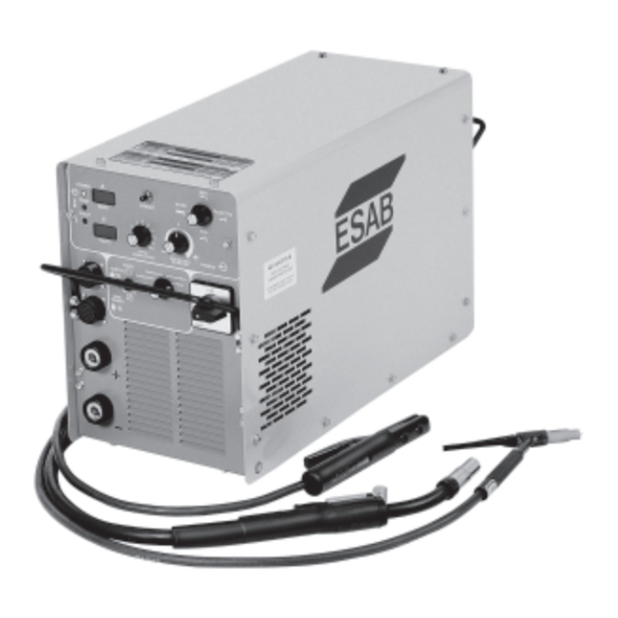
ESAB 350mpi
POWER SOURCE
F15-481-K
November, 2008
Advertisement
Table of Contents

Related Manuals for ESAB ESAB 350mpi


Summary of Contents for ESAB ESAB 350mpi
-
Page 1: Power Source
F15-481-K November, 2008 ESAB 350mpi POWER SOURCE P/N 36975 - 208-230/460 Vac 3-phase, 230 Vac 1-phase, 60 Hz P/N 36977 - 400/440 Vac 3-phase 50/60 Hz P/N 36976 - 575 Vac 3-phase, 60 Hz These INSTRUCTIONS are for experienced operators. If you are not fully familiar with the principles of operation and safe practices for arc welding equipment, we urge you to read our booklet, "Precautions and Safe Practices for Arc Welding, Cutting,... -
Page 2: User Responsibility
Some technical reference material is also provided to assist in basic troubleshooting the power source. If it is determined that the power supply is not operating properly, the operator should contact ESAB at (843) 664-4416 for assistance. The following is a list of terms/acronyms used throughout this manual. -
Page 3: Table Of Contents
TABLE OF CONTENTS SECTION TITLE PAGE PARAGRAPH USER RESPONSIBILITY ....................... SAFETY ........................ SECTION 1 DESCRIPTION ..................11 General ....................11 Duty Cycle ....................11 Volt-Ampere Curves ................11 SECTION 2 INSTALLATION ..................13 General ....................13 Required Tools ..................13 Unpacking and Placement .............. - Page 4 TABLE OF CONTENTS...
-
Page 5: Safety
SAFETY PRECAUTIONS WARNING: hese Safety Precautions are for 5. Do not use equipment beyond its ratings. For example, your protection. They summarize precaution- overloaded welding cable can overheat and create a fire ary information from the references listed in hazard. Additional Safety Information section. - Page 6 SAFETY PRECAUTIONS EQUIPMENT MAINTENANCE -- Faulty or FUMES AND GASES -- Fumes and improperly maintained equipment can gases, can cause discomfort or harm, cause injury or death. Therefore: particularly in confined spaces. Do not breathe fumes and gases. Shield- 1. Always have qualified personnel perform the installa- ing gases can cause asphyxiation.
- Page 7 PRÉCAUTIONS SÉCURITÉ a. Éloigner suffisamment tous les matériaux combus- AVERTISSEMENT: Ces règles de sécurité ont pour objet tibles du secteur où l’on exécute des soudures ou des d’ assurer votre protection. Veillez à lire et à observer les coupes à l’arc, à moins de les recouvrir complètement précautions énoncées ci-dessous avant de monter l’...
- Page 8 à empêcher la forma- 52529 “Precautions and Safe Practices for Arc Weld- tion de poches d’hydrogène, lesquelles présentent un ing, Cutting and Gouging” publié par ESAB. Nous danger d’explosion; ce ventilateur ne fonctionne que conseillons également de consulter les publications si l’interrupteur correspondant du panneau avant se...
- Page 9 PRECAUCION DE SEGURIDAD No use el equipo fuera de su rango de operación. Por ejemplo, el ADVERTENCIA: Estas Precauciones de Seguridad calor causado por cable sobrecarga en los cables de soldar son para su protección. Ellas hacen resumen de pueden ocasionar un fuego. información proveniente de las referencias listadas 6.
- Page 10 MANTENIMIENTO DEL EQUIPO -- Equipo HUMO Y GASES -- El humo y los defectuoso o mal mantenido puede gases, pueden causar malestar causar daño o muerte. Por lo tanto: daño, particularmente en espacios sin 1. Siempre tenga personal cualificado para efectuar l ventilación.
-
Page 11: Description
DESCRIPTION 1.1 GENERAL 1.2 DUTY CYCLE The ESAB 350mpi power source will operate on a 60% The ESAB 350mpi is a high performance constant duty cycle with a load of 350 amperes at 34 V dc (with voltage (CV) and constant current (CC) inverter power 3-phase input). -
Page 12: Section 1 Description
SECTION 1 DESCRIPTION NOTE: These measurements are made at the output termi- nals of the power source. Additional voltage "drops" will occur in the welding cable, torch cable, and in the workpiece. The use of proper size welding cable and secure electrical connections for the electrode and ground circuits will minimize these effects which ad- versely affect welding conditions and waste electrical... -
Page 13: Installation
2.1 GENERAL This section provides detailed instructions for the proper NOTE installation of the ESAB 350mpi power source from initial When lifting the ESAB 350mpi, apply direct upward receipt of the equipment to output welding connections. pressure to both of the carrying handles. Do not... -
Page 14: Input Connections
NOTE As shipped from the factory, the ESAB 350mpi, 400/ 440 V model, is set for 440 volts input. If you will be 2.4 INPUT CONNECTIONS operating the machine from a 400 V source, open... -
Page 15: Output Connections
Two male plug connectors (P/N 13792513) are sup- lead is at least twice as long as the input power plied with the ESAB 350mpi (see Figure 2-3). To leads on the inside of the power source (see Figure 2-3). Ensure the strain relief and ground connec-... - Page 16 SECTION 2 INSTALLATION Table 2-2. Typical Output Connections as close together as possible to limit this resistance. MIG Welding TIG Welding Stick Welding Make sure that the work cable (ground) is large enough, (DCRP) (DCSP) (DCSP or DCRP) kept as short as possible, properly insulated, securely connected to the workpiece, and that all connections positive (+) DCRP Electrode...
-
Page 17: Installation Section
SECTION 2 INSTALLATION Figure 2-4. Male Output Cable Connectors (P/N 13792513) (REMOTE CONTROL HC-5, P/N 34838) Figure 2-5. MIG (GMAW) Interconnection Diagram... - Page 18 SECTION 2 INSTALLATION (REMOTE CONTROL HC-5, P/N 34838) Figure 2-6. TIG (GTAW) Interconnection Diagram (REMOTE CONTROL HC-5, P/N 34838) REVERSE STRAIGHT PORALITY PORALITY (electrode positive) (electrode negative) ELECTRODE ELECTRODE (- Figure 2-7. Stick (SMAW) Interconnection Diagram...
-
Page 19: Operation
(FIGURE 3-1) Medium Slope Steep Slope A. WIRE FEEDER RECEPTACLE - For connecting NOTE: When the PROCESS CONTROL SWITCH is ESAB 42 & 115 vac wire feeders. set to the STICK, TIG, or TOUCH TIG modes, APPLICATION SELECT SWITCH has no effect on the welding output characteristics J. - Page 20 SECTION 3 OPERATION TIG, Touch TIG modes - - Depressing the E. DIGITAL VOLTS DISPLAY - In the normal PRESET SWITCH displays the output current mode, this large, easy to read digital display level in the AMPS window for the given indicates actual output voltage or preset voltage OUTPUT CONTROL setting.
-
Page 21: Mig / Gmaw (Cv) Operation
SECTION 3 OPERATION N. POWER ON/OFF SWITCH - Controls the main I. Set the ARC TRIM potentiometer to the center input power into the welding machine. In the “ON” position. The microprocessor will provide the position the machine is energized and power is optimum arc characteristics for each APPLI- available to all of the control circuits. -
Page 22: Stick / Smaw (Cc) Operation
SECTION 3 OPERATION G. Adjust the PANEL CURRENT potentiometer 3.5 STICK / SMAW (CC) OPERATION to the desired welding current by depressing the PRESET SWITCH and reading the value A. Make all secondary output connections to the in the AMPS DISPLAY. power source output receptacles as described in section 2 and as shown in the appropriate Note... -
Page 23: Overview Of Error Codes And Programs Updates
SECTION 3 OPERATION OVERVIEW OF ERROR CODES AND PROGRAM UPDATES Program Updates High input voltage. Over 264 VAC in 230 The current program is “PRG 1.04”. The program has mode, over 529 VAC in 460 mode, and over 661 VAC undergone 2 changes. - Page 24 SECTION 3 OPERATION...
-
Page 25: Maintenance
SECTION 4 MAINTENANCE 4.1 GENERAL 4.2 INSPECTION AND CLEANING If this equipment does not operate properly, stop work Since there are no moving parts (other than the fan) in immediately and investigate the cause of the malfunc- the power source, maintenance consist mainly of keep- tion. - Page 26 SECTION 4 MAINTENANCE...
-
Page 27: Troubleshooting
Go to next amps? step. ESAB 350mpi has passed the functionality check. Problem may be in interconnection of gas lines or polarity of output connectors. For technical assistance, refer to the Communication Guide located on the last page of this manual. - Page 28 SECTION 5 TROUBLESHOOTING...
- Page 29 REPLACEMENT PARTS SECTION 6 Replacement parts may be ordered from your ESAB 6.1 General distributor or from: Replacement parts are illustrated on the following ESAB Welding & Cutting Products figures. When ordering replacement parts, order by Attn.: Customer Service Dept.
- Page 30 REPLACEMENT PARTS SECTION 6...
- Page 31 Revision History Revision "A" added the Troubleshooting and Parts section. Revision "B" updated the Volt-Ampere Characteristics and Duty Cycles charts, made cor- rections in Installation and Operation sections and updated the Troubleshooting section. Revision "C" added the 575 V ac model. Revision "D"...
- Page 32 ESAB Welding & Cutting Products, Florence, SC Welding Equipment COMMUNICATION GUIDE - CUSTOMER SERVICES A. CUSTOMER SERVICE QUESTIONS: Order Entry Product Availability Pricing Delivery Order Changes Saleable Goods Returns Shipping Information Eastern Distribution Center Telephone: (800)362-7080 / Fax: (800) 634-7548...
-
Page 33: Replacement Parts
C:\Documents and Settings\rolfwa\Local Settings\Temp\A45E4A0A-2533-4D08-A5A0-2F103C35952F\36975.dwg 2 of 4... - Page 34 C:\Documents and Settings\rolfwa\Local Settings\Temp\A45E4A0A-2533-4D08-A5A0-2F103C35952F\36975.dwg 3 of 4...
- Page 35 C:\Documents and Settings\rolfwa\Local Settings\Temp\A45E4A0A-2533-4D08-A5A0-2F103C35952F\36975.dwg 4 of 4...
Need help?
Do you have a question about the ESAB 350mpi and is the answer not in the manual?
Questions and answers