Table of Contents

Subscribe to Our Youtube Channel
Related Manuals for ESAB Multimaster-260


Summary of Contents for ESAB Multimaster-260
- Page 1 F15-611-F INSTALLATION AND OPERATION for October, 2008 Multimaster-260 MIG/TIG/STICK WELDING PACKAGE Console - P/N 0558001513 (208/230 vac 1 Phase) Console - P/N 0558001514 (230/460/575 vac 1 Phase)
-
Page 2: User Responsibility
BE SurE ThIS INforMATIoN rEAChES ThE oPErATor. You CAN GET ExTrA CoPIES ThrouGh Your SuPPLIEr. CAuTIoN These INSTruCTIoNS are for experienced operators. If you are not fully familiar with the principles of operation and safe practices for arc welding and cutting equipment, we urge you to read our booklet, “Precautions and Safe Practices for Arc Welding, Cutting, and Gouging,”... -
Page 3: Table Of Contents
TABLE of CoNTENTS SECTIoN TITLE..............................PAGE SECTIoN 1 SAfETY PrECAuTIoNS .................................5 Safety Precautions ..................................5 Safety - English ...................................5 La seguridad - español................................9 La sûreté - français .................................. 13 SECTIoN 2 DESCrIPTIoN ..................................17 General ..................................... 17 RECEIVING-HANDLING ................................17 DESCRIPTION ................................... 17 OPTIONAL EQUIPMENT ................................ - Page 4 TABLE of CoNTENTS...
-
Page 5: Safety Precautions
SECTIoN 1 SAfETY PrECAuTIoNS Safety Precautions Safety - English WArNING: These Safety Precautions are fIrES AND ExPLoSIoNS -- heat from for your protection. They summarize pre- flames and arcs can start fires. hot cautionary information from the references slag or sparks can also cause fires and listed in Additional Safety Information sec- explosions. - Page 6 SECTIoN 1 SAfETY PrECAuTIoNS 1. Be sure the power source frame (chassis) is con- 3. Welders should use the following procedures to nected to the ground system of the input power. minimize exposure to EMF: 2. Connect the workpiece to a good electrical A.
- Page 7 SECTIoN 1 SAfETY PrECAuTIoNS 5. WArNING: This product, when used for welding 1. Always have qualified personnel perform the instal- or cutting, produces fumes or gases lation, troubleshooting, and maintenance work. which contain chemicals known to Do not perform any electrical work unless you are the State of California to cause birth qualified to perform such work.
- Page 8 SECTIoN 1 SAfETY PrECAuTIoNS 5. AWS C5.5 - "Recommended Practices for Gas Tung- sten Arc Welding“ 6. AWS C5.6 - "Recommended Practices for Gas Metal Arc Welding"“ 7. AWS SP - "Safe Practices" - Reprint, Welding Hand- book. 8. ANSI/AWS F4.1, "Recommended Safe Practices for Welding and Cutting of Containers That Have Held Hazardous Substances."...
-
Page 9: La Seguridad - Español
SECTIoN 1 SEGurIDAD Safety - Spanish La escoria puede estar caliente y desprenderse con velocidad. Personas cercanas deberán usar gafas ADVErTENCIA: Estas Precauciones de Se- de seguridad y careta protectora. guridad son para su protección. Ellas hacen resumen de información proveniente de las fuEGo Y ExPLoSIoNES -- El calor de referencias listadas en la sección "Información Adi- las flamas y el arco pueden ocacionar... - Page 10 SECTIoN 1 SEGurIDAD 1. Asegúrese de que el chasis de la fuente de poder 3. Los soldadores deberán usar los siguientes proced- esté conectado a tierra através del sistema de imientos para minimizar exponerse al EMF: electricidad primario. 2. Conecte la pieza de trabajo a un buen sistema de A.
- Page 11 SECTIoN 1 SEGurIDAD 5. ADVErTENCIA-- Este producto cuando se uti- 1. Siempre tenga personal cualificado para efec- liza para soldaduras o cortes, tuar l a instalación, diagnóstico, y mantenimiento produce humos o gases, los del equipo. No ejecute ningún trabajo eléctrico a cuales contienen químicos menos que usted esté...
- Page 12 SECTIoN 1 SEGurIDAD SIGNIfICADo DE LoS SIMBoLoS -- Según usted avanza en la lectura de este folleto: Los Símbolos Sig- nifican ¡Atención! ¡Esté Alerta! Se trata de su seguridad. Significa riesgo inmediato que, de no ser evadido, puede resultar inmediatamente en serio daño personal o la muerte.
-
Page 13: La Sûreté - Français
SECTIoN 1 SÉCurITÉ Safety - french INCENDIES ET ExPLoSIoNS -- La chaleur provenant des flammes ou de AVErTISSEMENT : Ces règles de sécurité l'arc peut provoquer un incendie. Le ont pour but d'assurer votre protection. Ils laitier incandescent ou les étincelles récapitulent les informations de précaution provenant des références dans la section peuvent également provoquer un... - Page 14 SECTIoN 1 SÉCurITÉ 1. Assurez-vous que le châssis de la source 3. Les soudeurs doivent suivre les procédures suivantes d'alimentation est branché au système de mise à pour minimiser l'exposition aux champs électriques la terre de l'alimentation d'entrée. et magnétiques : 2.
- Page 15 SECTIoN 1 SÉCurITÉ 5. AVErTISSEMENT : Ce produit, lorsqu'il est utilisé ENTrETIEN DE L'ÉQuIPEMENT -- un équipe- dans une opération de soudage ou de ment entretenu de façon défectueuse ou coupage, dégage des vapeurs ou des inadéquate peut causer des blessures gaz contenant des chimiques consid- graves ou mortelles.
- Page 16 SECTIoN 1 SÉCurITÉ SIGNIfICATIoN DES SYMBoLES Ce symbole, utilisé partout dans ce manuel, signifie "Attention" ! Soyez vigilant ! Votre sécurité est en jeu. DANGEr Signifie un danger immédiat. La situation peut entraîner des blessures graves ou mortelles. AVErTISSEMENT Signifie un danger potentiel qui peut entraîner des blessures graves ou mortelles.
-
Page 17: Description
SECTIoN 2 INTroDuCTIoN Table 1 Multimaster 260 Specifications Primary Input Voltage 208 Vac 230 Vac 460 Vac 575 Vac 1 Phase 1 Phase 1 Phase 1 Phase Primary Current @ 260 Amp @ 27 Volt 57 Amps 52 Amps 26 Amps 20 Amps @ 200 Amp @ 24 Volt 35 Amps... -
Page 18: Optional Equipment
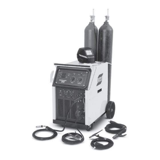
SECTIoN 2 INTroDuCTIoN 2.3.7 BuILT-IN TooL Box 2.3.2 PACKAGE CoN TENTS (STANDArD ACCESSorIES) The Multimaster 260 is designed with a lockable storage space Each Multimaster 260 package includes: on the left side of the machine for welding accessories such as • Power source with the built-in four roll drive wire feeder. - Page 19 SECTIoN 2 INTroDuCTIoN Choice of Argon or CO Regula- tor/Flowmeter 6’ Gas Hose Eyetech Auto- matic Helmet (Optional) Simple To Use Weld Controls Cylinder Safety Chain Large, Easy To Read Digital Displays for Wire Welding Gloves Speed, Amps and Volts (Optional) Simple and quick polarity change-over Factory Installed Two Cylinder Easy...
- Page 20 SECTIoN 2 INTroDuCTIoN Inductance Burnback Preflow/postflow Spot (Options) Hinged Wire Compartment Door Handle Cylinder Chain 4 Roll Drive Stand 2 Cylinder Low Mount Tray Adaptable Spindle Assembly Wheel Kit Installed Tool Box with Small Voltage Switch Parts Tray Compartment figure 1B - Components...
-
Page 21: Installation
SECTIoN 3 INSTALLATIoN 3.0 INSTALLATIoN 3.3 ELECTrICAL INPuT CoNNECTIoNS 3.1 LoCATIoN Several factors should be considered when selecting an in- stallation site. Adequate ventilation is necessary to provide Hex Bolt and Washer cooling, and the amount of dirt and dust to which the machine Sheetmetal Screws is exposed should be minimized. -
Page 22: Voltage Changeover
SECTIoN 3 INSTALLATIoN Input Conductor and fuse Size recommended full Primary Primary Load fuse Ground Input Input Line Size The termi nal labeled GrD is connected to the power source Conductor Volts Conductor Amperes chassis and is for ground purposes only. This must be Size Size connected to a good electrical ground. - Page 23 SECTIoN 3 INSTALLATIoN A. Release the pressure drive roll lever. Remove the two (2) screws holding the drive rolls to the Spool Spindle Locking Pin gears. C. Reverse the drive roll on the drive roll shaft. D. Replace the screws and tighten. Secure the pressure drive roll assembly.
-
Page 24: Connection Of Shielding Gas Supply
SECTIoN 3 INSTALLATIoN Flow Tube 3.7.4 SPooL BrAKE DrAG ADJuSTMENT Cylinder Valve Connection Spool brake disc friction should provide enough drag to keep the wire spool from spinning freely after wire feed stops. If adjustment is required, turn the adjusting screw inside the Control Valve spindle housing clockwise to increase drag or counterclock- wise to decrease it. -
Page 25: Operation
SECTIoN 4 oPErATIoN 4.0 oPErATIoN 4.1.9 WIrE fEED SPEED CoNTroL (fIGurE 12) 4.1 STANDArD CoNTroLS The wire feed speed control potentiometer allows wire feed speed adjustments between 65 and 675 inches per minute 4.1.1 PoWEr oN/off SWITCh & LAMP (IPM). Selecting the Mig process and pressing the PRESET The main power switch is located on the front panel in the switch allows the wire feed speed to be preset in the top digital display by turning the wire speed knob. - Page 26 SECTIoN 4 oPErATIoN Preset WFS - IPM Button Lamp Weld Process Amps Switch Digital Meters Lamp Voltage Set - MIG Amps/Volts/WFS Current Set - STICK/TIG Power “ON” Lamp Temperature Lamp Fault Lamp Wire Feed Speed Trim figure 12 - Control Panel Mig Gun Trigger Main...
-
Page 27: Optional Controls
SECTIoN 4 oPErATIoN 4.2.2 PrEfLoW/PoSTfLoW/SPoT/BurNBACK 4.2 oPTIoNAL CoNTroLS (oPTIoNAL) PN-0558001795 (fIGurE 15) 4.2.1 INDuCTANCE TrIM (oPTIoNAL) This optional control is mounted in place of the standard PN-0558001794 (figure 14) burnback control inside the wire spool compartment. A description of the module follows: Inductance is used to optimize short circuiting arc perfor- mance by changing the current rise and fall time of each A. -
Page 28: Operating Procedures
SECTIoN 4 oPErATIoN 4.2.3 rEMoTE CoNTroL MoDuLE (oPTIoNAL) 4.3 oPErATING ProCEDurES PN-0558001792 (fIGurE 16) This optional control panel mounts to the front of the power source to the right of the main power switch (see Figure 13). The remote receptacle can be used for a variety of options, such as a Tig current control, foot pedal control or manual Comply with all ventilation, fire and other safety require- hand current control. - Page 29 SECTIoN 4 oPErATIoN hANDLING ThE TorCh workpiece in order for the arc to start. As soon as the arc is Starting the Arc struck, withdraw the electrode approximately 1/8 inch above There is nothing difficult or technical about starting an are in the workpiece to avoid contaminating the electrode in the the proper manner.
-
Page 30: Mig Welding Set-Up
SECTIoN 4 oPErATIoN 4.4 MIG WELDING SET-uP WHEN THE PROCESS SWITCH IS PLACED IN THE MIG POSITION THE MULTIMASTER 260 IS SET TO TURN ”ON” WHEN THE MIG GUN TRIGGER IS DEPRESSED. Step 1. Choose the weld parameters based of the wire alloy, diameter, material thickness and shielding gas from Table 3 - MIG PARAMETERS CHART. -
Page 31: Section 4 Operation
SECTIoN 4 oPErATIoN Table 3 - MIG PArAMETErS ChArT (Cont’d) Note 1: When using 100% CO sheilding gas, add 2 volts to the data table value. -
Page 32: Tig Welding Setup
Step 1. Determine the weld parameters based on the metal VOLTAGE/CURRENT knob to the desired weld thickness in Table 4 or use the ESAB TIG Welding Hand- current on the top digital display window. book (optional) for suggested welding parameters. -
Page 33: Stick Welding Set-Up
SECTIoN 4 oPErATIoN 4.6 STICK WELDING SET-uP Step 3. Place the WELD PROCESS 3 switch in the STICK (right) position. WHEN THE PROCESS SWITCH IS PLACED IN THE STICK POSITION, THE MULTIMASTER 260 TURNS “ON” THE WELD CONTACTOR SO THAT POWER IS IMMEDIATELY AVAILABLE Step 4. - Page 34 SECTIoN 4 oPErATIoN...
-
Page 35: Maintenance
SECTIoN 5 MAINTENANCE 5.0 MAINTENANCE 5.1 MAINTENANCE AND SErVICE If uNINSuLATED CABLE AND PArTS ArE NoT rEPLACED, AN ArC CAuSED BY A BArE CABLE or PArT TouChING A GrouNDED SurfACE MAY DAMAGE uNProTECTED EYES BE SurE ThAT ThE BrANCh CIrCuIT or MAIN DISCoN- or STArT A fIrE. - Page 36 SECTIoN 5 MAINTENANCE 5.2.1.3 TrANSforMEr 5.2.2 WIrE fEEDEr Occasional blowing out of the dust and dirt from around the As soft wire is fed, the drive rolls may pick up metal from the transformer is recommended. This should be done periodi- wire surface.
-
Page 43: Replacement Parts
To ensure proper operation, it is recommended that only genuine ESAB parts and products be used with this equipment. The use of non-ESAB parts may void your warranty. Replacement parts may be ordered from your ESAB Distributor. - Page 44 SECTIoN 6 rEPLACEMENT PArTS 20, 21 figure 24 - right Side front View TorCh ADAPTor ASSEMBLY (Internal View) TorCh ADAPTor ASSEMBLY 26,27 (External View)
- Page 45 SECTIoN 6 rEPLACEMENT PArTS figure 24 - right Side front View (Con’t) QTY. ITEM CIrCuIT rEQ. DESCrIPTIoN SYMBoL 952895 SWITCH PB NORMALLY OPEN 672831 SWITCH TOGGLE SPDT 951474 SWITCH SEALL BLACK 0558001702Y BRACKET RH HANDLE 13730632 POT LIN 10.0K 2.00W .88L R1,R2 0558001019 KNOB 1.57 DIA.
- Page 46 COVER BOTTOM RIGHT 0558001689Y COVER BOTTOM LEFT 0558001686G BASE PLATE 0558001696G CYLINDER TRAY 13734588 LABEL ESAB 5.56 x 9.6 0558001578 LATCH HASP 0558001585 LATCH HASP STRIKE 0558001690Y TOOL BOx DOOR (HINGE & HINGE BKACKET NOT INCLUDED) 0558001856G UPPER CYLINDER SUPPORT BRACKET...
- Page 47 SECTIoN 6 rEPLACEMENT PArTS figure 26 - Inside right View of Multimaster 260 QTY. ITEM CIrCuIT rEQ. DESCrIPTIoN SYMBoL 948258 SPINDLE MOLDED (SEE FIGURE 28) 0558001685G REAR COVER 0558001533 TRANSISTORS (FET) CHOPPER 240A 250V Q1-3 38186 PCB ASSY. DRIVER PCB3 0558001893 POWER CABLE 208/230V 0558002081...
- Page 48 SECTIoN 6 rEPLACEMENT PArTS 64,65 67, 68 figure 27 - Inside Left View of Multlimaster 260 QTY. ITEM CIrCuIT rEQ. DESCrIPTIoN SYMBoL 0558001710G FAN MOUNT 680970 MOTOR 950592 FAN BLADE 0558001577 MAIN TRANSFORMER 208/230V 0558001580 MAIN TRANSFORMER - 230/460/575V 99511915 DIODE REV 200V 250A D1,2 99511916...
- Page 49 SECTIoN 6 rEPLACEMENT PArTS figure 28 - Spindle Assembly for Migmaster 2606 QTY. ITEM CIrCuIT rEQ. DESCrIPTIoN SYMBoL 0558002561M BRACKET WIRE SPOOL MOUNT 65509512 RIV BLD AL 1/4-GRIP .062-.250 0558002548M SHELF DIVIDER 634347 CLIP HITCH .16D x 3.25L 948258 SPINDLE MOLDED 36756 “D”...
- Page 50 SECTIoN 6 rEPLACEMENT PArTS DRIVE ROLLS (See Drive Roll & Guide Tube Selection Giude on Page 23) figure 29 - Auto-Lift Mini four roll Geared Wire Drive System - 0558001339 QTY. QTY. ITEM DESCrIPTIoN ITEM PArT No DESCrIPTIoN PArT No 0558001752 Spacer Tube Boogie 0558001743...
- Page 51 SECTIoN 6 rEPLACEMENT PArTS Drive roll and Guide Tube Selection Wire Type Guide Tube roll Drive* & Diameter hard Wires (“V” groove) .023 in. (0.6 mm) 21155 0558001499 .030 in. (0.8 mm) 21155 0558001499 .035 in. (0.9 mm) 21156 0558001498 .045 in.
- Page 52 NoTES...
- Page 53 NoTES...
- Page 54 NoTES...
-
Page 55: Revision History
rEVISIoN hISTorY Revision - 08/2007 - Changed Specifications in Sect 2 - Process: MIG (GMAW), Open Circuit Voltage (max): from: 70 Vdc to: 39.0 Vdc per D. Perkins. Made various updates to manual format. Updated front cover picture per B. Bitzky. Revision 03 / 2008 - Added Input Conductor and Fuse Size table in Section 3. - Page 56 ESAB Welding & Cutting Products, florence, SC Welding Equipment CoMMuNICATIoN GuIDE - CuSToMEr SErVICES A. CUSTOMER SERVICE QUESTIONS: Telephone: (800)362-7080 / fax: (800) 634-7548 hours: 8:00 AM to 7:00 PM EST Order Entry Product Availability Pricing Order Information Returns B. ENGINEERING SERVICE:...
Need help?
Do you have a question about the Multimaster-260 and is the answer not in the manual?
Questions and answers