Table of Contents
Advertisement
INSTRUCTION MANUAL
DC WELDING POWER SOURCES
This manual provides complete instructions for the following power sources:
ESAB 230/460 vac, 3 ph., 60 Hz
ESAB 230/460/575 vac, 3ph., 60 Hz
ESAB 220/400 vac, 3 ph., 50 Hz
ESAB 220/400 vac, 3 ph., 50 Hz, CE
These INSTRUCTIONS are for experienced operators. If you are not fully familiar with the
principles of operation and safe practices for arc welding equipment, we urge you to read our
booklet, "Precautions and Safe Practices for Arc Welding, Cutting, and Gouging," Form 52-
529. Do NOT permit untrained persons to install, operate, or maintain this equipment. Do NOT
attempt to install or operate this equipment until you have read and fully understand these
instructions. If you do not fully understand these instructions, contact your supplier for further
information. Be sure to read the Safety Precautions before installing or operating this
equipment.
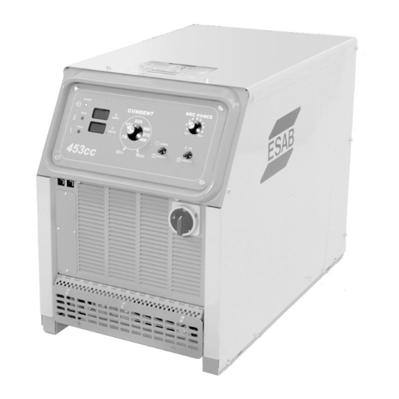
453cc & 553cc
453cc
Item No.
453cc - 0558001274
453cc - 0558001275
453cc - 0558001276
453cc - 0558001277
F-15-591-A
February, 2001
553cc
Item No.
553cc - 0558001278
553cc - 0558001279
553cc - 0558001280
553cc - 0558001281
Advertisement
Table of Contents
Troubleshooting

Related Manuals for ESAB 453cc


Summary of Contents for ESAB 453cc
- Page 1 INSTRUCTION MANUAL 453cc & 553cc DC WELDING POWER SOURCES This manual provides complete instructions for the following power sources: ESAB 230/460 vac, 3 ph., 60 Hz ESAB 230/460/575 vac, 3ph., 60 Hz ESAB 220/400 vac, 3 ph., 50 Hz ESAB 220/400 vac, 3 ph., 50 Hz, CE These INSTRUCTIONS are for experienced operators.
-
Page 2: User Responsibility
This equipment will perform in conformity with the description thereof contained in this manual and accompa- nying labels and/or inserts when installed, operated, maintained and repaired in accordance with the instruc- tions provided. This equipment must be checked periodically. Malfunctioning or poorly maintained equipment should not be used. -
Page 3: Table Of Contents
SECTION PARAGRAPH TITLE SAFETY ENGLISH SAFETY PRECAUTIONS ... 4, 5 FRENCH SAFETY PRECAUTIONS ... 6, 7 SECTION 1 DESCRIPTION ... 8 General ... 8 Receiving-Handling ... 8 Description ... 8 1.3.1 Power Source ... 8 1.3.2 Volt-Ampere Characteristics ... 9 Optional Accessories ... -
Page 4: English Safety Precautions
WARNING: hese Safety Precautions are for your protection. They summarize precaution- ary information from the references listed in Additional Safety Information section. Before performing any installation or operating procedures, be sure to read and follow the safety precautions listed below as well as all other manuals, material safety data sheets, labels, etc. - Page 5 FUMES AND GASES -- Fumes and gases, can cause discomfort or harm, particularly in confined spaces. Do not breathe fumes and gases. Shield- ing gases can cause asphyxiation. Therefore: 1. Always provide adequate ventilation in the work area by natural or mechanical means. Do not weld, cut, or gouge on materials such as galvanized steel, stainless steel, copper, zinc, lead, beryllium, or cadmium unless posi- tive mechanical ventilation is provided.
-
Page 6: Précautions De Sécurité
PRÉCAUTIONS DE SÉCURITÉ AVERTISSEMENT: Ces règles de sécurité ont pour objet d’ assurer votre protection. Veillez à lire et à observer les précautions énoncées ci-dessous avant de monter l’ équipement ou de commercer à l’utiliser. Tout défaut d’observation de ces précautions risque d’entraîner des blessures graves ou mortelles. - Page 7 PRÉCAUTIONS DE SÉCURITÉ levage, des câbles de grue ou divers chemins électriques. g. Empêchez l’apparition de toute humidité, notamment sur vos vêtements, à la surface de l’emplacement de travail, des câbles, du porte-électrode et du poste de soudage/coupage. Réparez immédiatement toute fuite d’eau.
-
Page 8: Description
(200-volt), the output is derated to 36 volts @ 400 amps (453cc) and to 38 volts @ 500 amps (553cc). The 453cc and 553cc 50 Hz may operate from 380 vac or 415 vac primary input when using the 400 vac change over connection. When using this connection, the output voltage is derated from 38 v to 36 v (453cc) and 42 v to 38 v (553cc). -
Page 9: Volt-Ampere Characteristics
Figure 1.1 Volt/Ampere Curves MAX. OUTPUT MIN. OUTPUT 453CC MAX. OUTPUT 1.4 OPTIONAL ACCESSORIES Stick Electrode Holder Assembly (21226) Includes holder, 15-ft. cable, and twist lock connector. -
Page 10: Section 2 Installation
SECTION 2 2.1 LOCATION A proper installation site is necessary for the power source to provide dependable service. A proper instal- lation site permits freedom of air movement through the unit while minimizing exposure to dust, dirt, moisture, and corrosive vapors. A minimum of 18 inches (46 cm) is required between the side and rear panels of the power source and the nearest obstruction. - Page 11 Line Fuses Rated Input 100% Duty Cycle Rating Conductor* Volts Am ps 453CC 482cc 553CC 582cc * Sized per National Code for 75 C rated copper conductors @ 40 Not more than three conductors in a raceway or cable. Local codes should be followed if they specify sizes other than those listed above.
-
Page 12: Secondary (Output) Welding Connections
SECTION 2 D. Check all connections for proper tightness. En- sure all connections are correct and well insu- lated. E. Figure 2-2 illustrates the input voltage terminal board and the input voltage link connections. The particular voltages from which this power source may be operated are stated on the rating plate. - Page 13 SECTION 2 INSTALLATION Figure 2.3 CONTROL CONNECTIONS POWER CKT. BREAKERS, SWITCH 10A 32VDC, 250VAC 600V OUTPUT RECEPTACLE 2.4...
-
Page 14: Section 3 Operation
This control allows the operator to adjust the output current. Placing the Panel/Remote switch in the RE- MOTE position disables the current control on the front panel. 3.1.7 3.1.4 Figure 3.1 Control Locations (453cc illustrated) OPERATION 3.1.5 3.1.2 3.1.3 3.1.1... -
Page 15: Over Temperature Indicator
SECTION 3 3.1.6 Over Temperature Indicator (Temp) This amber light will indicate when an internal overheat- ing condition has occurred and one of the thermal switches has opened. User control of the solid state contactor will be interrupted and power source output will shut down to protect critical components. -
Page 16: Section 4 Maintenance
SECTION 4 4.1 GENERAL If this power source does not operate properly, stop work immediately and investigate the cause of the malfunction. Maintenance work must be per- formed by an experienced person, and electrical work by a trained electrician. Do not permit un- trained persons to inspect, clean, or repair this power source. -
Page 17: Section 5 Troubleshooting
SECTION 5 5.1 GENERAL DISCONNECT primary power at wall switch, or circuit breaker, before attempting inspection or work inside the power source. If the power source is operating improperly, the follow- ing troubleshooting information may be used to locate the source of the trouble. Check the problem against the symptoms in the follow- ing troubleshooting guide (Table 5-2.) The remedy for the problem may be quite simple. -
Page 18: Section 5 Troubleshooting
SECTION 5 CONDITION ACTION Unit Inoperative No input power. Check main line (user's) switch fuses -- replace if needed. B. Poor or improper input (terminal board) connections. C. Defective on/off switch on front panel -- replace. D. Main transformer overheating. Also check for proper cooling, proper primary hookup, or shorted turn on secondary. -
Page 19: Section 6 Parts
SECTION 6 6.1 GENERAL Always provide the series or serial number of the unit on which the parts will be used. The serial number is stamped on the unit nameplate. 6.2 ORDERING To assure proper operation, it is recommended that only genuine ESAB parts and products be used with this equipment. - Page 26 SECTION 6 REPLACEMENT PARTS...
- Page 27 SECTION 6 REPLACEMENT PARTS...
- Page 28 SECTION 6 REPLACEMENT PARTS...
-
Page 29: Replacement Parts
XFMR MAIN 230/460 553CC XFMR MAIN 230/460/575V 553CC1T1 XFMR MAIN 220/400 553CC1T1 INDUCTOR SCHEMATIC DIAG 453CC/553CC 50/60HZ WIRING DIAG PRI 3 PH AFRAME 453CC/553CC WIRING DIAG SECONDARY 453CC/553CC 50/60HZ KIT WIRE PRI 453CC KIT WIRE PRIMARY 553CC KIT WIRE SEC 453CC/553CC... - Page 31 BRACKET TERMINAL BOARD MTG BAFFLE BAFFLE BLANKING PLATE KNOB 01.37 A PANEL TOP TUBING INSULATING VINYL 105' C RATING 9" LG TUBING HEAT SHRINKABLE 6" LG CE FILTER ASSY STAND OFF 1/4-20 X .75 HINGE ACCESS PANEL ACCESS GRAY LABEL THREE PHASE...
- Page 32 ESAB Welding & Cutting Products, Florence, SC Welding Equipment A. CUSTOMER SERVICE QUESTIONS: Order Entry Order Changes B. ENGINEERING SERVICE: Telephone: (843) 664-4416 / Fax : (800) 446-5693 Welding Equipment Troubleshooting Warranty Returns C. TECHNICAL SERVICE: Telephone: (800) ESAB-123/ Fax: (843) 664-4452 Part Numbers Performance Features D.
Need help?
Do you have a question about the 453cc and is the answer not in the manual?
Questions and answers