ESAB MultiPower 460 Pulse Instruction Manual
Dc welding power source
Hide thumbs
Also See for MultiPower 460 Pulse:
- Instruction manual (40 pages) ,
- Instruction manual (60 pages)
Table of Contents

Subscribe to Our Youtube Channel
Related Manuals for ESAB MultiPower 460 Pulse


Summary of Contents for ESAB MultiPower 460 Pulse
- Page 1 MultiPower 460 Pulse DC WELDING POWER SOURCE INSTRUCTION MANUAL This manual provides complete instructions for the following power sources starting with Serial Number MxxJ211xxx, March 2002: ESAB ITEM NO. 0558002877 0558004165 02 / 2007...
-
Page 2: User Responsibility
BE SURE THIS INFORMATION REACHES THE OPERATOR. YOU CAN GET EXTRA COPIES THROUGH YOUR SUPPLIER. These INSTRUCTIONS are for experienced operators. If you are not fully familiar with the principles of operation and safe practices for arc welding and cutting equipment, we urge you to read our booklet, "Precautions and Safe Practices for Arc Welding, Cutting, and Gouging,"... -
Page 3: Table Of Contents
TABLE OF CONTENTS SECTION TITLE PAGE SECTION 1 SAFETY .............................. 5 SECTION 2 DESCRIPTION ............................ 11 SECTION 3 INSTALLATION ..........................19 SECTION 4 OPERATION ............................25 SECTION 5 MAINTENANCE ..........................35 SECTION 6 REPLACEMENT PARTS ........................43... - Page 4 TABLE OF CONTENTS...
-
Page 5: Safety
SECTION 1 SAFETY PRECAUTIONS WARNING: hese Safety Precautions are for 5. Do not use equipment beyond its ratings. For example, your protection. They summarize precaution- overloaded welding cable can overheat and create a fire ary information from the references listed in hazard. -
Page 6: Safety Precautions
SECTION 1 SAFETY PRECAUTIONS FUMES AND GASES -- Fumes and EQUIPMENT MAINTENANCE -- Faulty or im- gases, can cause discomfort or harm, properly maintained equipment can cause particularly in confined spaces. Do injury or death. Therefore: not breathe fumes and gases. Shield- ing gases can cause asphyxiation. - Page 7 SECTION 1 PRECAUCION DE SEGURIDAD ADVERTENCIA: Estas Precauciones de Seguridad usted esta entrenado para su uso. son para su protección. Ellas hacen resumen de No use el equipo fuera de su rango de operación. Por ejemplo, el calor información proveniente de las referencias listadas causado por cable sobrecarga en los cables de soldar pueden en la sección "Información Adicional Sobre La ocasionar un fuego.
- Page 8 SECTION 1 PRECAUCION DE SEGURIDAD HUMO Y GASES -- El humo y los gases, MANTENIMIENTO DEL EQUIPO -- Equipo pueden causar malestar daño, defectuoso o mal mantenido puede causar particularmente en espacios sin ventilación. daño o muerte. Por lo tanto: No inhale el humo o gases.
- Page 9 SECTION 1 PRÉCAUTIONS DE SÉCURITÉ AVERTISSEMENT: Ces règles de sécurité ont pour objet coupes à l’arc, à moins de les recouvrir complètement d’ assurer votre protection. Veillez à lire et à observer les d’une bâche non-inflammable. Ce type de matériaux précautions énoncées ci-dessous avant de monter l’...
- Page 10 52529 “Precautions and Safe Practices for Arc présentent un danger d’explosion; ce ventilateur ne Welding, Cutting and Gouging” publié par ESAB. fonctionne que si l’interrupteur correspondant du Nous conseillons également de consulter les publica- panneau avant se trouve placé en position ON tions sui-vantes, tenues à...
-
Page 11: Description
This manual has been prepared for use by an experienced operator. It provides information to familiarize the operator with the design, installation and operation of the MultiPower 460 Pulse power source. DO NOT attempt to install or operate this equipment until you have read and fully understood these instructions. - Page 12 Tig (GTAW) and arc gouging in the CC (constant current) mode. Features • Auto Fan - The MultiPower 460 Pulse fan will run when the power source is first powered up for approximately 30 seconds. The fan will start again when welding begins and is at a current level above 50 amps.
- Page 13 (Refer to Figures 2-3 and 2-4) 1. FAULT LAMP The RED fault light on the MultiPower 460 Pulse front panel indicates a problem with set-up parameters. A "Steady" light "On" indicates there is no program for the material and wire diameter selected. A "Blinking"...
- Page 14 SECTION 2 DESCRIPTION When using a DuraDrive 4-30 or DuraDrive 4-48 Wire Feeder, the wire feed speed is displayed in inches per minute (IPM) in the top display when the PRESET button is pressed and the wire speed adjustment knob on the wire feeder is rotated.
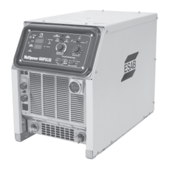
- Page 15 D. POWER SOURCE FRONT PANEL DESCRIPTION (Refer to Figure 2-5) Main Power On/Off Switch Control Panel Circuit Breakers CB1 & 2 19-Pin Wire Feeder Connection Contactor On/Off Switch Remote Pendant Connection 115 Vac 10 Amps Receptacle Output Connections Figure 2-5. MultiPower 460 Pulse...
- Page 16 This pendant (Figure 2-6) provides remote output control and a contactor closure switch to close the contactor making the output terminals “hot”. The PANEL/REMOTE switch on the MultiPower 460 Pulse control panel must be placed in the REMOTE position when using this accessory. The pendant has the capability to change weld processes as well as adapt to digital and analog wire feeders.
- Page 17 SECTION 2 DESCRIPTION NOTE When using the MP-460 Pulse, the STANDARD/PULSE switch must be in STANDARD position proportional current control using a TIG remote current device (FC-5B or TC- 2B). NOTE The FC-5B foot control or TC-2B hand control must be used with the MP-460 for remote current Tig current control.
- Page 18 SECTION 2 DESCRIPTION...
-
Page 19: Installation
SECTION 3 INSTALLATION 3. INSTALLATION A. LOCATION A proper installation site is necessary for the power source to provide dependable service. A proper installation site permits freedom of air movement through the unit while minimizing exposure to dust, dirt, moisture, and corrosive vapors. - Page 20 SECTION 3 INSTALLATION ELECTRIC SHOCK CAN KILL! Before making electrical input connections to the power source, "Machinery Lockout Procedures" should be em- ployed. If the connections are to be made from a line disconnect switch, place the switch in the off position and padlock it to prevent inadvert- ent tripping.
- Page 21 SECTION 3 INSTALLATION 2. Remove the top cover. Identify primary power input connection block, chassis ground lug on the fan shroud frame, and primary input terminal board. Refer to Figures 3-1 and 3-2. 3. When using the provided strain relief, refer to Figure4-2 for proper cable strip lengths.
-
Page 22: Section 3 Installation
SECTION 3 INSTALLATION 6. Figures 3-3, 3-4 and 3-5 illustrate the input voltage terminal boards and the input voltage link connections. The particular voltages from which this power source may be operated are stated on the rating plate. The voltage links were factory set for highest voltage stated on the rating plate (575VAC). If the power source is to be operated on another stated input voltage, the links must be reset for that particular input voltage. - Page 23 1. CONNECTIONS FROM THE WIRE FEEDER The wire feeder control cable connects to the 19 pin J1 receptacle on the lower front left of the MultiPower 460 Pulse. The secondary output cable connects (in most cases) between the positive output lug of the MultiPower 460 Pulse and the power connection block of the wire feeder.
- Page 24 SECTION 3 INSTALLATION...
-
Page 25: Operation
A. WIRE FEEDER COMPATIBILITY safety hazards, improper cooling may The MultiPower 460 Pulse power source can be used with several ESAB 42 cause damage to the components. volt wire feeders. The model wire feeder being used will determine the setup Keep side panels and top closed when unit is energized. -
Page 26: Section 4 Operation
Step 1. Connect wire feeder to MultiPower 460 Pulse and set PANEL/RE- MOTE switch to REMOTE position. - Page 27 When the PROCESS switch is placed in the TIG position, the MultiPower 460 remote current Tig current control. Pulse is automatically set for CC (constant current) welding using the ESAB Touch TIG starting method. The voltage and current at the output lugs is maintained at low values until the electrode is shorted to the workpiece.
- Page 28 SECTION 4 OPERATION Arc Force is automatically enabled when the WELD PROCESS switch is set to the STICK position. The level of Arc Force is automatically adjusted by the current preset being used. When the WELD PROCESS switch is moved to the TIG or STICK position, Step 1.
- Page 29 SECTION 4 OPERATION Step 5. CV-Carbon Arc Gouging Only - Place the Process Switch in the MIG position and the Contactor Toggle switch to the "ON" position. See Figures 4-4 and 4-5. When the WELD PROCESS switch is moved to the TIG or STICK position, Step 6.
-
Page 30: Operation Section
Mig welding means that pulse parameters (such as pulse height, pulse width, background current and pulse frequency) are automatically adjusted by the MultiPower 460 Pulse as the wire feed speed is changed by the operator. A unique non-synergic Mig pulse mode is also offered for welding applications and wire feeder combinations that cannot use the preprogrammed synergic pulse data. - Page 31 When the PROCESS switch is placed in the MIG position and the STANDARD/PULSE switch is place in the PULSE position, the MultiPower 460 Pulse is set for CC over CC (constant current) pulse Mig welding. The power source will output open circuit voltage (OCV) when the Mig Gun trigger is depressed.
- Page 32 SECTION 4 OPERATION Step 6. Set the shielding gas flow rate to 35 cfh by activating the gas purge switch on the wire feeder or pulling the gun trigger and turning the adjustment knob on the Flowmeter Step 7 Set the voltage knob on the wire feeder to the "5" or center 12 o'clock position.
- Page 33 6. NON-SYNERGIC PULSE OPERATION The MultiPower 460 Pulse has the unique ability to Pulse MIG weld in the NON- Note: SYNERGIC mode. Non-synergic operation means the pulse parmeters can be...
-
Page 34: Operation Section
Jumper Plug Removed and Harness connected Non-Synergic Mode - The pulse parameters are determined by the position of the pulse selection switches, the MultiPower 460 Pulse TRIM knob and Wire Feed Speed preset. Figure 4-7 Jumper Plug Removed and Harness Connected... -
Page 35: Maintenance
SECTION 5 MAINTENANCE 5.0 MAINTENANCE AND TROUBLESHOOTING A. CLEANING Periodically, remove the cover from the power source and blow accumulated dust and dirt from the air passages and interior components by using clean low pressure air. The frequency of cleaning required depends upon the environment in which the power source is used. - Page 36 SECTION 5 MAINTENANCE Table 5-1 Troubleshooting Guide CONDITION ACTION Unit Inoperative No input power. Check main line (user's) switch fuses -- replace if needed. Poor or improper input (terminal board) connections. Defective on/off switch -- replace. Thermal light on. Main transformer overheating. Also check for proper cooling, proper primary hookup, or shorted turn on secondary.
- Page 37 Schematic Diagram Section 1 - MultiPower 460 - 230/460/575V...
- Page 38 Schematic Diagram Section 2 - MultiPower 460 - 230/460/575V...
- Page 39 Schematic Diagram Section 3 - MultiPower 460 - 230/460/575V...
- Page 40 Wiring Diagram Section 1 - MultiPower 460 - 230/460/575V...
- Page 41 Wiring Diagram Section 2 - MultiPower 460 - 230/460/575V...
- Page 42 Wiring Diagram Section 3 - MultiPower 460 - 230/460/575V...
-
Page 43: Replacement Parts
The serial number is stamped on the unit nameplate. ORDERING To assure proper operation, it is recommended that only genuine ESAB parts and products be used with this equip- ment. The use of non-ESAB parts may void your warranty. - Page 44 SECTION 6 REPLACEMENT PARTS 4, 5 QTY. ITEM CIRCUIT REQ. DESCRIPTION SYMBOL 0558002877 MultiPower 460 Pulse 678025 Terminal Assembly 952219 Outlet 110V (Square) 952937 Connection Box Rcpt. 14FS X-ROT 634515 SW TGGL SPDT 2 Pos 14A 125V Q/D S3, 5...
- Page 45 11, 7 6, 7 2, 3 QTY. ITEM CIRCUIT REQ. DESCRIPTION SYMBOL 0558002877 MultiPower 460 Pulse 678025 Terminal Assembly 0558001818 Knob 1.31 Dia. (B) 13730632 Pot Lin *10.0K 2.00W 0.88L (A & B) R1, R2 952895 Switch PB Normally Open...
- Page 46 REPLACEMENT PARTS QTY. ITEM CIRCUIT REQ. DESCRIPTION SYMBOL 0558002877 MultiPower 460 Pulse 0558002892 Switch Toggle 4PDT 0558001818 Knob, Ribbed 954945 Overlay, Multipower 460 Pulse 634515 Switch TGGL SPDT 2 POS 14A 124V Q/D 951474 Switch Seal, Black 0558002667 Panel, Control Pulse...
- Page 47 SECTION 6 REPLACEMENT PARTS QTY. ITEM CIRCUIT REQ. DESCRIPTION SYMBOL 0558002877 MultiPower 460 Pulse 13732733 Label for Install Use COP Wire 950219 Relief Strain 2" (Non-enclosed) 0558001371 Panel Top Kydex Env 0558001370 Panel Left Side Kydex Env...
- Page 48 SECTION 6 REPLACEMENT PARTS QTY. ITEM REQ. DESCRIPTION SYMBOL 0558002877 MultiPower 460 Pulse 99511916 Diode Fwd 200V 250A 99511915 Diode Rev 200V 250A 954864 Label 3 Phase 2062334 Fan Motor 1/3 HP 1625 RPM 954699 Label Warning Fan Hazard 36173 Blade Fan 14"...
- Page 49 SECTION 6 REPLACEMENT PARTS QTY. ITEM REQ. DESCRIPTION SYMBOL 0558002877 MultiPower 460 Pulse 17280110 Res WW Fix'd ST 100W 5% 100.00 R3, R4 0558002712 Transformer 230/460/575V 672065 Strap Terminal 36110 Board Input Terminal 230/460/575V...
- Page 50 SECTION 6 REPLACEMENT PARTS QTY. ITEM REQ. DESCRIPTION SYMBOL 0558002877 MultiPower 460 Pulse 952938 SCR 480V 18A Panel MNT 951997 Transducer Current 951085 SW THML D/T 176 15A 120V Q/D 0558003077 IGBT 600V/300A Q1, 2, 3 951940 Capacitor 1.0uf 600VDC 10%...
- Page 51 Revision History Original release on February 12, 2003 02 / 2004 revision - Added note on Page 33 concerning Non-Synergic pulse operation. 10 / 2004 revision - Updated wiring diagram (0558003064) per CN# 043141. 02 / 2007 revision - Updated 0558003034 Schematic from Rev. B to Rev. C per Dave Perkins 23FEB07 e-mail.
- Page 52 ESAB Welding & Cutting Products, Florence, SC Welding Equipment COMMUNICATION GUIDE - CUSTOMER SERVICES A. CUSTOMER SERVICE QUESTIONS: Telephone: (800)362-7080 / Fax: (800) 634-7548 Hours: 8:00 AM to 7:00 PM EST Order Entry Product Availability Pricing Order Information Returns B. ENGINEERING SERVICE:...
Need help?
Do you have a question about the MultiPower 460 Pulse and is the answer not in the manual?
Questions and answers