Table of Contents
Advertisement
Quick Links
Advertisement
Table of Contents

Related Manuals for Planet IVR-100 Series


Summary of Contents for Planet IVR-100 Series
- Page 1 Industrial VPN Security Router IVR-100 & IVR-300 Series Quick Installation Guide...
-
Page 2: Table Of Contents
Table of Contents 1. Package Contents ..................3 2. Connecting The Power Input ..............4 2.1 Upper Panel ..................4 2.2 Wiring the Power Inputs..............5 2.3 Grounding the Device ................7 2.4 Wiring the Fault Alarm Contact ............7 2.5 Wi-Fi Antenna Installation (IVR-300W) ..........8 3. -
Page 3: Package Contents
1. Package Contents Thank you for purchasing PLANET Industrial Security Gateway, IVR-100 and IVR-300 series. The descriptions of these models are as follows IVR-100 Industrial 5-Port 10/100/1000T VPN Security Gateway Industrial 5-Port 10/100/1000T VPN Security Gateway with IVR-300 Redundant Power Industrial 5-Port 10/100/1000T + 802.11ax Wi-Fi VPN Security... -
Page 4: Connecting The Power Input
2. Connecting The Power Input This section describes the functionalities of the VPN Gateway’s components. 2.1 Upper Panel The upper panel of the IVR-100 consists of one terminal block connector within two DC power inputs. Figure 2-1 shows the upper panel of the IVR-100 VPN Gateway. Max. -
Page 5: Wiring The Power Inputs
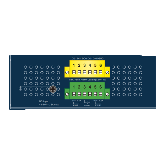
The Upper Panel of the IVR-300FP series consists of two terminal block connectors. - Green terminal block connector: Power 1, Power 2 input and relay alarm output - Yellow terminal block connector: 2 digital input and 2 digital output Figure 2-3 shows the upper panel of the IVR-300FP VPN Gateway. DI1 DO0 DO1 1 2 3 4 5 6 Max. - Page 6 Please make sure the input voltage is under the specification of the Security Gateway. 2. Tighten the wire-clamp screws for preventing the wires from loosening. Fault/ Power 1 Power 2 Alarm The wire gauge for the terminal block should be in the range between 12 and 24 AWG.
-
Page 7: Grounding The Device
2.3 Grounding the Device User MUST complete grounding wired with the device; otherwise, a sudden lightning could cause fatal damage to the device. Earth Ground DI1 DO0 DO1 1 2 3 4 5 6 Max. Fault Alarm Loading: 24V, 1A 1 2 3 4 5 6 DC Input: 48-54V... -
Page 8: Wi-Fi Antenna Installation (Ivr-300W)
1. The wire gauge for the terminal block should be in the range between 12 and 24 AWG. 2. Alarm relay circuit accepts up to 24V, max. 1A currents. 2.5 Wi-Fi Antenna Installation (IVR-300W) Step 1: Fasten the two dual-band antennas to the antenna connectors on the front panel of the IVR-300W. -
Page 9: Hardware Installation
3. Hardware Installation This section guides you to installing the VPN Gateway on the DIN-rail and wall. Basic knowledge of networking is assumed. Please read this chapter completely before continuing. The installation procedures of the IVR-100 & IVR-300 series are the same as the ones shown below. -
Page 10: Side Wall-Mount Plate Mounting
3.3 Side Wall-mount Plate Mounting You must use the screws supplied with the wall-mounting brackets. Damage caused to the parts by using incorrect screws would invalidate your warranty. -
Page 11: Setup Of The Vpn Gateway
4. Setup of the VPN Gateway 4.1 Requirements Please confirm the following items before configuration: 1. Please confirm the network is working properly: It is strongly suggested to test your network connection by connecting your computer directly to ISP. 2. Suggested operating systems: Windows 10/11. 3. Recommended web browsers: Google Microsoft Edge/Chrome/Firefox. 4.2 Logging in to the VPN Gateway Then refer to the steps below to configure the VPN Gateway: Step 1: Connect the IT administrator’s PC and VPN Gateway’s LAN port (port... - Page 12 Step 2: The browser prompts you for the login credentials. (Both are “admin” by default.) Default IP address: 192.168.1.1 Default user name: admin Default password: admin Default 2.4GHz SSID: PLANET_2.4G (for IVR-300W) Default 5GHz SSID: PLANET_5G (for IVR-300W) Figure 4-2: Web Login Screen The following web screen is based on the IVR-300W;...
- Page 13 After filling out the new account and password, the main screen appears as shown in Figure 4-3. Figure 4-4: Web Main Screen Now, you can use the Web management interface to continue the Security Gateway management or manage the Security Gateway by console interface. Please refer to the user’s manual for more.
-
Page 14: Recovering Back To Default Configuration
5. Recovering Back to Default Configuration 5.1 IP Address has been changed or admin password has been forgotten – To reset the IP address to the default IP address “192.168.1.1” or reset the login password to default value, press the hardware reset button on the front panel for about 10 seconds. -
Page 15: Appendix
6. Appendix Appendix A: Default Setting Default IP Address 192.168.1.1 Default Login User Name admin Default Login Password admin Default DHCP Server Default LAN Port Ethernet Ports 1-4 Default WAN Port Ethernet Port 5 Default 2.4G SSID (for IVR-300W) PLANET_2.4G Default 5G SSID (for IVR-300W) PLANET_5G Appendix B: User’s Manual... -
Page 16: Customer Support
7. Customer Support Thank you for purchasing PLANET VPN Gateway. The above steps introduce the simple configuration of the VPN Gateway. If you have other questions, please contact the local dealer where you purchased this product or you can contact PLANET directly at the following email address: support@planet.com.tw.
Need help?
Do you have a question about the IVR-100 Series and is the answer not in the manual?
Questions and answers