Sign In
Upload
Download
Table of Contents
Contents
Add to my manuals
Delete from my manuals
Share
URL of this page:
HTML Link:
Bookmark this page
Add
Manual will be automatically added to "My Manuals"
Print this page
×
Bookmark added
×
Added to my manuals
Manuals
Brands
Planet Manuals
Network Router
ISW-500T
User manual
Planet ISW-500T User Manual
Industrial 5-/8-port 10/100tx compact ethernet switch
Hide thumbs
Also See for ISW-500T
:
User manual
(17 pages)
1
Table Of Contents
2
3
4
5
6
7
8
9
10
11
12
13
14
15
16
page
of
16
Go
/
16
Contents
Table of Contents
Bookmarks
Table of Contents
Table of Contents
1 Package Contents
2 Product Features
3 Product Specifications
4 Hardware Introduction
Three-View Diagram
Front View
Led Definition
Wiring the Power Inputs
Wiring the Fault Alarm Contact
5 Installation
DIN-Rail Mounting Installation
Wall-Mount Plate Mounting
Customer Support
Advertisement
Quick Links
1
Package Contents
2
Wiring the Fault Alarm Contact
3
Customer Support
Download this manual
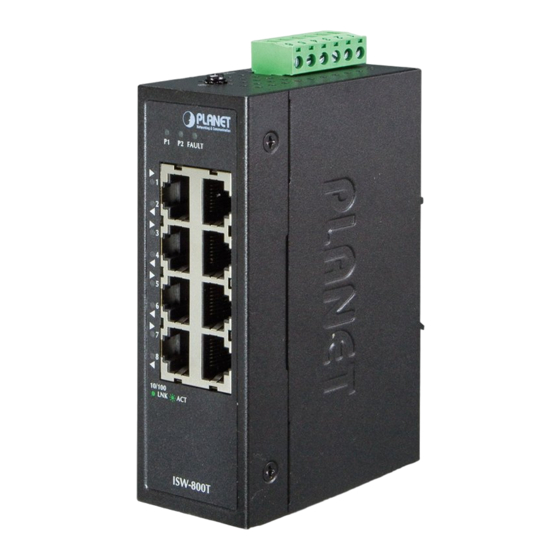
Industrial 5-/8-Port 10/100TX
Compact Ethernet Switch
ISW-500T/ISW-800T
User's Manual
Table of
Contents
Previous
Page
Next
Page
1
2
3
4
5
Advertisement
Table of Contents
Need help?
Do you have a question about the ISW-500T and is the answer not in the manual?
Ask a question
Questions and answers
Related Manuals for Planet ISW-500T
Switch Planet ISW-500T User Manual
Industrial 5-18-port compact ethernet switch (17 pages)
Network Router Planet ISW-800M User Manual
Planet technology isw-800m 8-port managed industrial ethernet switch user's manual (57 pages)
Network Router Planet ISW-802M User Manual
6-port 10/100mbps tp+2-port 100base-fx managed industrial ethernet switch (60 pages)
Network Router Planet ISW-621 Series User Manual
4-port 10/100mbps +1/2 100fx fiber port industrial fast ethernet switch (28 pages)
Network Router Planet ISW-800T User Manual
Industrial 5-/8-port 10/100tx compact ethernet switch (16 pages)
Network Router Planet ADSL 2/2+ VoIP Router IAD-200W User Manual
Adsl 2/2+ voip router (111 pages)
Network Router Planet IGS-801T User Manual
5/8-port 10/100/1000mbps industrial gigabit ethernet switch (24 pages)
Network Router Planet IGS-501 User Manual
5/8-port 10/100/1000mbps industrial gigabit ethernet switch (24 pages)
Network Router Planet IGS-20040MT User Manual
L2+ multi-port full gigabit managed ethernet switch (381 pages)
Network Router Planet IGS-10020 Series User Manual
L2+ multi-port full gigabit managed ethernet switch (409 pages)
Network Router Planet IRT-1001ST User Manual
Remote access router (152 pages)
Network Router Planet IGS-5225-16T4S User Manual
Industrial l2+ gigabit ethernet managed switch igs-5225 series (391 pages)
Network Router Planet IGS-5225-20T4C2X Quick Installation Manual
Industrial l2+ 20-port 10/100/1000t + 4-port tp/sfp combo + 2-port 10g sfp+ managed ethernet switch (-40~75 degrees c) (16 pages)
Network Router Planet IGS-620TF User Manual
Industrial 4-port 10/100/1000base-t + 2-slot 100/1000base-x sfp ethernet switch (36 pages)
Network Router Planet IGS-604HPT-M12 Quick Installation Manual
Industrial ip67-rated 4-port 10/100/1000t; 802.3at poe + 2-port 10/100/1000t m12 managed ethernet switch (-40~75 degrees c) (16 pages)
Network Router Planet IGS-4215-16T2S Quick Installation Manual
Industrial 16-port 10/100/1000t + 2-port 100/1000x sfp managed gigabit ethernet switch (16 pages)
This manual is also suitable for:
Isw-800t
Table of Contents
Print
Rename the bookmark
Delete bookmark?
Delete from my manuals?
Login
Sign In
OR
Sign in with Facebook
Sign in with Google
Upload manual
Upload from disk
Upload from URL


Need help?
Do you have a question about the ISW-500T and is the answer not in the manual?
Questions and answers