
Related Manuals for Planet IGS-620TF


Summary of Contents for Planet IGS-620TF
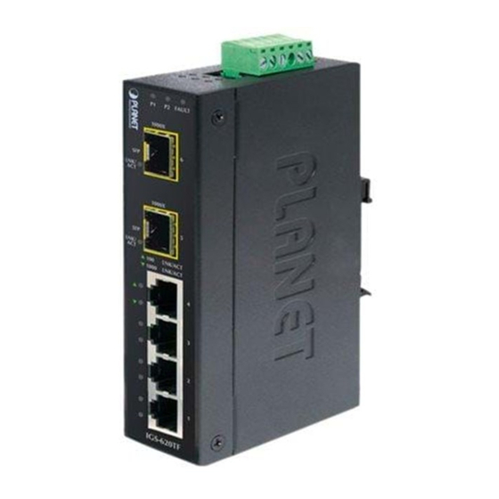
- Page 1 Industrial 4-Port 10/100/1000BASE-T + 2-Slot 100/1000BASE-X SFP Ethernet Switch IGS-620TF User's Manual...
-
Page 2: Fcc Warning
PLANET has made every effort to ensure that this User’s Manual is accurate; PLANET disclaims liability for any inaccuracies or omissions that may have occurred. -
Page 3: Ce Mark Warning
Do not dispose of WEEE as unsorted municipal waste; they should be collected separately. Revision PLANET Industrial 4-port 10/100/1000BASE-T + 2-slot 100/1000BASE-X SFP Ethernet Switch User's Manual For Model: IGS-620TF Revision: 1.1 (April, 2015) -
Page 4: Table Of Contents
Table of Contents 1. Introduction ................5 1.1 Package Contents ............... 5 1.2 How to Use This Manual ............5 1.3 Product Features ..............6 1.4 Product Specifications ............7 1.5 Physical Dimensions ............9 2. Installation ................10 2.1 Product Description ............10 2.1.1 Switch Front Panel ...........12 2.1.2 LED Indicators ............13 2.1.3 Switch Upper Panel ..........14... -
Page 5: Introduction
The term “Industrial Gigabit Ethernet Switch” mentioned in this user’s manual also means the IGS-620TF. 1.2 How to Use This Manual This... -
Page 6: Product Features
Appendix A This chapter contains cable information of the Industrial Gigabit Ethernet Switch. 1.3 Product Features Physical Port 4-Port 10/100/1000BASE-T RJ45 with auto MDI / MDI-X function 2 SFP interfaces, 100/1000BASE-X dual mode (DIP switch control) Layer 2 Features ... -
Page 7: Product Specifications
When primary port link fails, the traffic will swap to backup port automatically. Once the primary port status is back to link up, the traffic swaps from backup port to primary port. 1.4 Product Specifications Model IGS-620TF Hardware Specifications 10/100/1000BASE-T Ports 2 1000BASE-SX/LX/BX SFP interfaces SFP Interfaces... - Page 8 Throughput 8.9Mpps (packet per second) Maximum 9216bytes Transmission Unit 10/100/1000BASE-T : Cat. 3, 4, 5, 5e, 6 UTP cable (100meters, max.) EIA/TIA-568 100-ohm STP (100meters, max.) 1000BASE-SX : 50/125μm or 62.5/125μm multi-mode fiber optic cable, up to 550m/2km (vary on SFP module) 1000BASE-LX : Network Cables...
-
Page 9: Physical Dimensions
1.5 Physical Dimensions IGS-620TF Industrial Gigabit Ethernet Switch dimensions (W x D x H): 135 x 87 x 32mm Side View PWR1 Fault PWR2 Port 5 Port 6 Mode Port 5 100FX 1000X Port 6 100FX 1000X Fiber Mode Redundant... -
Page 10: Installation
Adjustable 6-Port Switch Mode or 4 + 2 Fiber Redundant Mode Via the built-in DIP switch, the IGS-620TF can be configured as 6-Port Ethernet switch or 4+2 fiber redundant mode. With the 6-Port switch mode, the IGS-620TF can operate in Store-and-Forward mechanism with high performance;... - Page 11 Being able to operate under the temperature range from -40 to 75 degrees C, the IGS-620TF can be placed in almost any difficult environment. The compact, IP-30 standard metal case of IGS-620TF allows either DIN rail or wall mounting for efficient use of cabinet space.
-
Page 12: Switch Front Panel
2.1.1 Switch Front Panel Figure 2-1 shows the front panel of Industrial Gigabit Ethernet Switch. P2 FAULT 1000X LNK / 1000X LNK / LNK/ACT 1000 LNK/ACT IGS-620TF Figure 2-1: IGS-620TF Front Panel... -
Page 13: Led Indicators
2.1.2 LED Indicators System Color Function Green Lit: indicates power 1 has power. Green Lit: indicates power 2 has power. Lit: indicates either power 1 or power 2 has no FAULT Green power. Per 10/100/1000T Port Color Function Lit: indicates the link through that port is successfully established at 100Mbps or 10Mbps. -
Page 14: Switch Upper Panel
2.1.3 Switch Upper Panel The upper panel of the Industrial Gigabit Ethernet Switch consists of one terminal block connector within two DC power inputs, and also provides 3 DIP switches for 100/1000X fiber support on two SFP slots and fiber redundant function. Figure 2-2 shows the upper panel of the Industrial Gigabit Ethernet Switch. -
Page 15: Wiring The Power Inputs
Chapter 2.1.7 Redundancy Overview. If using Switch mode, the IGS-620TF can use 6 ports. If using Redundant mode, the one of two Fiber port will use for redundant. So the only 5 ports is using. Note 2.1.4 Wiring the Power Inputs The 6-contact terminal block connector on the top panel of Industrial Gigabit Ethernet Switch is used for two DC redundant power inputs. -
Page 16: Wiring The Fault Alarm Contact
The wire gauge for the terminal block should be in the range between 12 and 24 AWG. Note 2.1.5 Wiring the Fault Alarm Contact The fault alarm contacts are in the middle of the terminal block connector as the picture shows below. Inserting the wires, the Industrial Gigabit Ethernet Switch will detect the fault status of the power failure and then forms an open circuit. - Page 17 The Industrial Gigabit Ethernet Switch has two SFP interfaces that support 100/1000 dual speed mode (Optional Multi-mode / Single- mode 100BASE-FX / 1000BASE-SX/LX SFP module) through DIP switch setting. Cabling Each 10/100/1000BASE-T port uses RJ45 sockets -- similar to phone jacks -- for connection of unshielded twisted-pair cable (UTP).
- Page 18 Approved PLANET SFP Transceivers PLANET Industrial Gigabit Ethernet Switch supports 100/1000 dual mode with both single mode and multi-mode SFP transceivers. The following list of approved PLANET SFP transceivers is correct at the time of publication: Gigabit SFP Transceiver Modules...
- Page 19 SFP-Port 1000BASE-LX (WDM,TX:1310nm) mini-GBIC MGB-LA40 module - 40km SFP-Port 1000BASE-LX (WDM,TX:1550nm) mini-GBIC MGB-LB40 module - 40km SFP-Port 1000BASE-LX (WDM,TX:1310nm) mini-GBIC MGB-LA60 module - 60km SFP-Port 1000BASE-LX (WDM,TX:1550nm) mini-GBIC MGB-LB60 module - 60km SFP-Port 1000BASE-SX mini-GBIC module - 550m MGB-TSX (-40~75°C) SFP-Port 1000BASE-LX mini-GBIC module - 10km MGB-TLX (-40~75°C)
- Page 20 - 40km (-40~75°C) SFP-Port 100BASE-BX Transceiver (WDM,TX:1550nm) MFB-TFB40 - 40km (-40~75°C) It is recommended to use PLANET SFPs on the Industrial Gigabit Ethernet Switch. If you insert an SFP transceiver that is not supported, the Industrial Gigabit Ethernet Note Switch will not recognize it.
- Page 21 1. Set the DIP Switch of SFP Port 1 or Port 2 to the “OFF” position with fiber speed 1000BASE-X. Port 5 (DIP 1) 100FX 1000X Port 6 (DIP 2) 100FX 1000X 2. Make sure both sides of the SFP transceiver are with the same media type, example:...
- Page 22 2. Make sure both sides of the SFP transceiver are with the same media type or WDM pair, for example, 100BASE-FX to 100BASE-FX, 100BASE-BX20-U to 100BASE-BX20-D. 3. Check whether the fiber-optic cable type matches with the SFP transceiver model. To connect to MFB-FX SFP transceiver, use the multi-mode fiber cable, with one side being the male duplex LC connector type.
-
Page 23: Redundancy Overview
Never pull out the module without pulling the lever or the push bolts on the module. Directly pulling out the module with force could damage the module and the SFP module slot of the Industrial Gigabit Ethernet Note Switch. 2.1.7 Redundancy Overview The Industrial Gigabit Ethernet Switch provides rapid fiber redundancy of link for highly critical Ethernet applications. -
Page 24: Mounting Installation
Manual uses IGS-801 (PLANET 8 Port Industrial Gigabit Switch) as the example. However, the steps for PLANET Industrial Note Switch & Industrial Media Converter are similar. 2.2.1 Installing DIN-rail Mounting The DIN-rail is screwed on the Industrial Gigabit Ethernet Switch when out of factory. - Page 25 Step 2: Lightly insert the bottom of the switch into the track. Step 3: Make sure if the DIN-rail is tightly secured on the track. Step 4: Please refer to the following procedures to remove the Industrial Gigabit Ethernet Switch from the track. Step 5: Lightly pull out the bottom of the switch for removing it from the track.
-
Page 26: Wallmount Plate Mounting
2.2.2 Wallmount Plate Mounting To install the Industrial Gigabit Ethernet Switch on the wall, please follow the instructions described below. Step 1: To remove the DIN-Rail from the Industrial Gigabit Ethernet Switch, loosen the screws to remove the DIN-rail. Step 2: Place the wallmount plate on the rear panel of the Industrial Gigabit Ethernet Switch. -
Page 27: Applications
3. Applications In this paragraph, we will describe how to install the Industrial Gigabit Ethernet Switch. Public Construction Gigabit Fiber Switch IGS-620TF 1000 20km Serial Device 70km IGS-620TF Server IP Camera 120km 1000 1000 Control Center Outdoor Outdoor IP Camera... - Page 28 Harsh Climate Weather Station Desert IP Camera IP Camera IP Camera IGS-620TF 120km IP Camera 1000 IGS-620TF 30km 1000 Fiber Switch 70km Data Center 30km 1000 1000 IGS-620TF IP Camera IP Camera 30km 1000 30km 120km 30km 1000 1000 1000...
- Page 29 Installation Steps Step 1: Unpack the Industrial Gigabit Ethernet Switch. Step 2: Check whether the DIN-Rail is screwed on the Industrial Gigabit Ethernet Switch. (Please refer to DIN-Rail Mounting section for DIN-Rail installation if the DIN-Rail is not screwed on the Industrial switch). If you want to wallmount the Industrial Gigabit Ethernet Switch, please refer to the Wallmount Plate...
-
Page 30: Switch Operation
4. Switch Operation 4.1 Address Table The Industrial Gigabit Ethernet Switch is implemented with an address table. This address table is composed of many entries. Each entry is used to store the address information of some node in network, including MAC address, port no, etc. This information comes from the learning process of Industrial Gigabit Ethernet Switch. -
Page 31: Auto-Negotiation
checking before transmission. Therefore, no error packets will occur. It is the best choice when a network needs efficiency and stability. The Industrial Gigabit Ethernet Switch scans the destination address from the packet-header, searches the routing table provided for the incoming port and forwards the packet, only if required. The fast forwarding makes the switch attractive for connecting servers directly to the network, thereby increasing throughput and availability. -
Page 32: Troubleshooting
5. Troubleshooting This chapter contains information to help you solve issues. If the Industrial Gigabit Ethernet Switch is not functioning properly, make sure the Industrial Gigabit Ethernet Switch was set up according to instructions in this manual. The per port LED is not lit Solution: Check the cable connection of the Industrial Gigabit Ethernet Switch. -
Page 33: Cable Connection Parameters
6. Cable Connection Parameters The wiring details are as shown below: 100FX (Full Duplex) Fiber Optic Cables: Standard Fiber Type Cable Specification 100BASE-FX Multi-mode 50/125μm or 62.5/125μm (1300nm) Multi-mode 50/125μm or 62.5/125μm 100BASE-FX (1310nm) Single-mode 9/125μm 100BASE-BX-U Single-mode 9/125μm (TX : 1310/RX : 1550) 100BASE-BX-D (TX : 1550/RX : 1310) 1000X Fiber Optic Cables:... -
Page 34: Appendix A: Networking Connection
APPENDIX A: Networking Connection A.1 Switch’s RJ45 Pin Assignments 1000Mbps, 1000BASE-T Contact MDI-X BI_DA+ BI_DB+ BI_DA- BI_DB- BI_DB+ BI_DA+ BI_DC+ BI_DD+ BI_DC- BI_DD- BI_DB- BI_DA- BI_DD+ BI_DC+ BI_DD- BI_DC- 10/100Mbps, 10/100BASE-TX RJ-45 Connector pin assignment MDI-X Contact Media Dependent Interface- Media Dependent Interface Cross Tx + (transmit) -
Page 35: Rj45 Cable Pin Assignments
A.2 RJ45 Cable Pin Assignments The standard RJ45 receptacle/connector There are 8 wires on a standard UTP/STP cable and each wire is color- coded. The following shows the pin allocation and color of straight cable and crossover cable connection: Straight Cable SIDE 1 SIDE 2 SIDE 1... -
Page 36: Ec Declaration Of Conformity
*Model Number : IGS-620TF * Produced by: Manufacturer Name : Planet Technology Corp. Manufacturer Address : 10F., No.96, Minquan Rd., Xindian Dist., New Taipei City 231, Taiwan (R.O.C.) is herewith confirmed to comply with the requirements set out in the Council Directive on the Approximation of the Laws of the Member States relating to Electromagnetic Compatibility Directive on (2004/108/EC).
Need help?
Do you have a question about the IGS-620TF and is the answer not in the manual?
Questions and answers